
Electromagnetic switch protective structure and mounting method thereof

A technology of electromagnetic switch and protective structure, which is applied in the direction of electromagnetic relay, detailed information of electromagnetic relay, circuit, etc., can solve the problems of inability to provide the impedance of external pollutants entering the moving part of the moving iron core of the electromagnetic switch, and can not be effectively realized, so as to achieve increase Thickness, increased wear strength, enhanced sealing effect

Inactive Publication Date: 2013-12-04
芜湖杰诺瑞汽车电器系统有限公司
View PDF3 Cites 2 Cited by
  • Summary
  • Abstract
  • Description
  • Claims
  • Application Information

AI Technical Summary

Problems solved by technology

[0004] At present, most of the structures of electromagnetic switches only provide lubrication for the moving mechanism of the internal moving iron core, such as adding oil-containing anti-friction bushings, adding grease, etc. Under relatively harsh operating environments, the existing electromagnetic switch structures cannot provide The effective control of the impedance of the moving part of the electromagnetic switch moving iron core to the entry impedance of external pollutants cannot effectively realize the minimum control of the accumulation of internal wear pollutants due to the entry of external pollutants

Method used


Image

  • Electromagnetic switch protective structure and mounting method thereof
  • Electromagnetic switch protective structure and mounting method thereof
  • Electromagnetic switch protective structure and mounting method thereof

Examples


Embodiment Construction

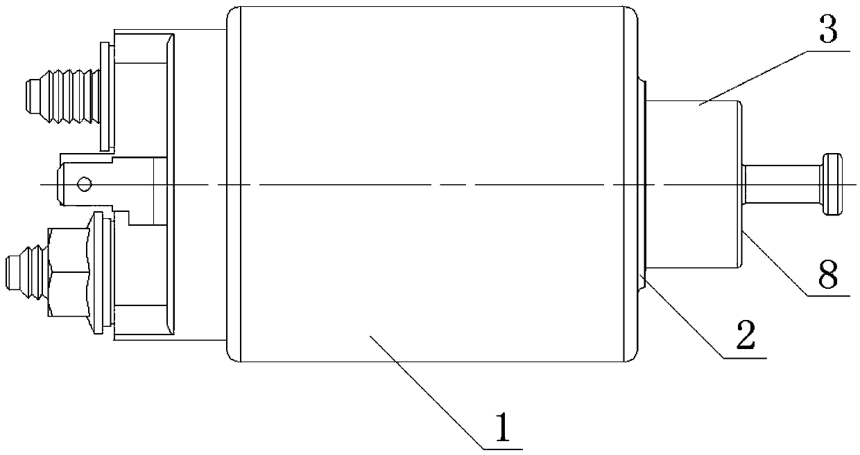
[0023] figure 1 It is a schematic diagram of the structure of the prior art. The moving part of the internal moving iron core is prone to failure due to the entry of pollutants. For example, if muddy water and oil enter the interior, it will lead to poor contact between the moving contact and the static contact, and the contact will spark. Sintering, or in winter because the electromagnetic switch moving iron core freezes and there is no response when starting; after dust and iron filings enter, it will directly cause the moving iron core of the electromagnetic switch to be stuck with gray iron, and the starter cannot work normally or ignite After the switch is powered off, the driving gear cannot be reset and is dragged back by the flywheel of the engine, or at the same time, because the moving iron core is stuck, the moving contact and the static contact cannot be powered off, the starter is ablated, the battery is momentarily grounded, and the wiring harness Ablation or eve...


PUM


Abstract

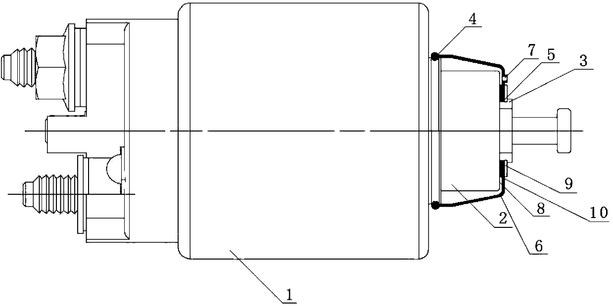
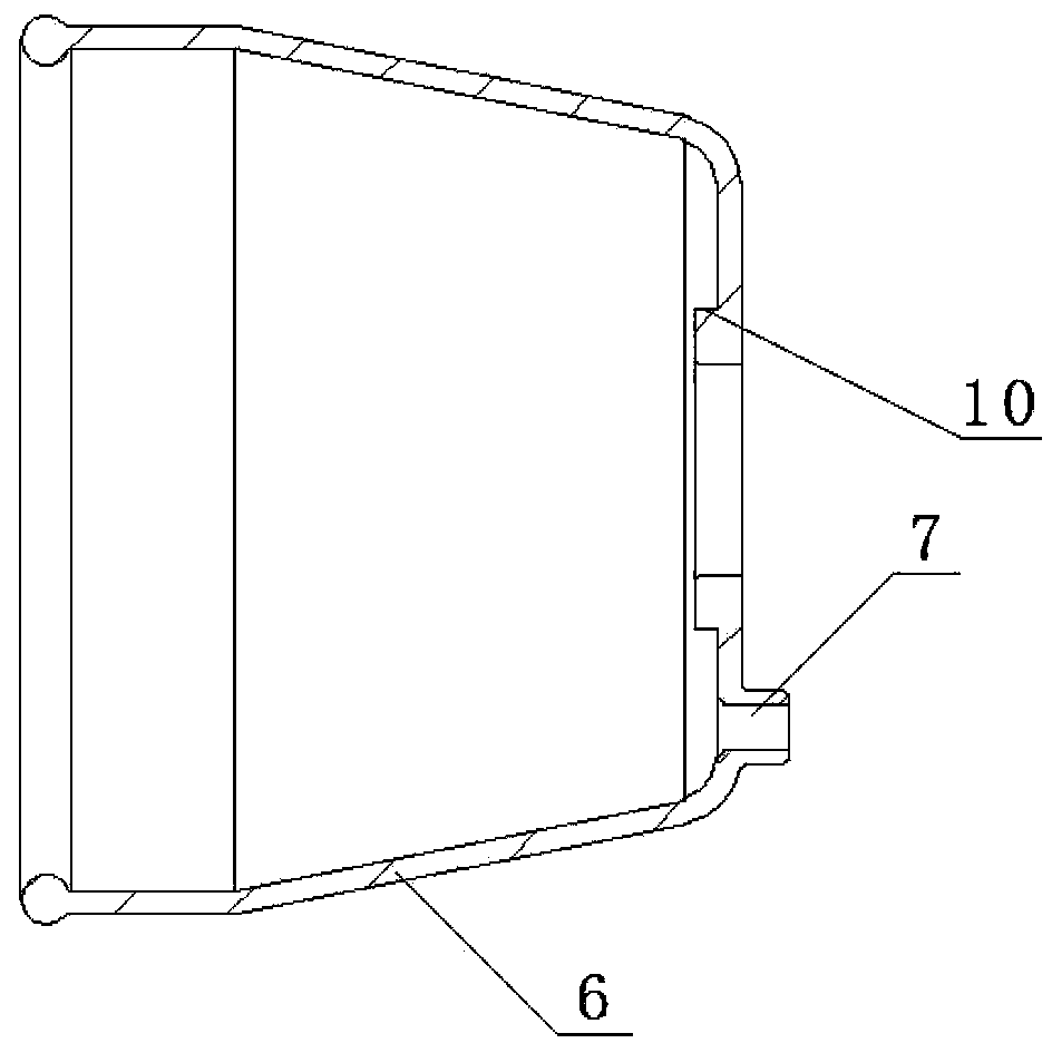
The invention discloses an electromagnetic switch protective structure and a mounting method thereof. The electromagnetic switch protective structure comprises an electromagnetic switch body (1), a guide cylinder (2) mounted on the electromagnetic switch body (1), and an movable iron core draw bar (3) mounted on a movable iron core end surface (8). The guide cylinder (2) is provided with a U-shaped positioning snapping groove (4), and the movable iron core draw bar (3) is provided with a positioning snapping groove (5). The electromagnetic switch protective structure also comprises a bowl-shaped rubber sealing cover (6), the bottom of the bowl-shaped rubber sealing cover (6) is provided with a central hole, the portion of the central hole is snapped inside the positioning snapping groove (5), and an opening end is mounted inside the U-shaped positioning snapping groove (4). According to the electromagnetic switch protective structure, the U-shaped positioning snapping groove and the positioning snapping groove achieve the positioning of the bowl-shaped rubber sealing cover and further achieve the sealing of the periphery of the guide cylinder to complete the protection to the movement of the movable iron core of an electromagnetic switch; meanwhile, an air exhaust device on the bowl-shaped rubber sealing cover can well release the negative pressure of the electromagnetic switch.

Description

technical field [0001] The invention relates to an electromagnetic switch in the technical field of compression ignition engine starters, in particular to a protective structure of the electromagnetic switch and an installation method thereof. Background technique [0002] The role of the electromagnetic switch in the application of the starter is the most important, which ensures the smooth meshing of the starter drive gear and the engine flywheel and the return after power failure, as well as the timely on-off of the main contact of the electromagnetic switch. The electromagnetic switch is a contactor. In the actual operation, the start switch is turned on, and the electromagnetic switch is energized. Since the direction of the current passing through the attracting coil and the holding coil is the same, the direction of the magnetic force generated is the same. Under the joint action of the magnetic force of the two coils, the moving iron The core moves against the force ...

Claims


Application Information

Patent Timeline
IPC IPC(8): H01H50/00H01H49/00
Inventor 丁国华彭召辉秦川杨二珍
Owner 芜湖杰诺瑞汽车电器系统有限公司
Learn More