
Direct-current permanent-magnet planar motion platform

A motion platform and permanent magnet plane technology, which is applied in the direction of electric components, electrical components, electromechanical devices, etc., can solve the problems of complex structure of the motion platform, unsuitable volume and weight, etc., so as to reduce production cost and assembly difficulty, load Lightweight, the effect of improving movement precision

Inactive Publication Date: 2013-12-04
贾莉莉
View PDF4 Cites 0 Cited by
  • Summary
  • Abstract
  • Description
  • Claims
  • Application Information

AI Technical Summary

Problems solved by technology

[0003] In order to solve the problem that the existing motion platform has a complex structure and is not suitable for occasions requiring smaller volume and weight, and the contradiction between reducing manufacturing costs and improving precision, a DC permanent magnet planar motion platform is proposed

Method used


Image

  • Direct-current permanent-magnet planar motion platform
  • Direct-current permanent-magnet planar motion platform
  • Direct-current permanent-magnet planar motion platform

Examples


Embodiment Construction

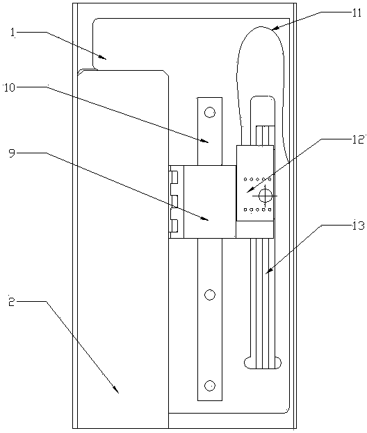
[0007] combine figure 1 as well as figure 2 Describe the implementation of the single linear module mover force. In this embodiment, it consists of a base 1, a permanent magnet stator, and a mover coil 3; the permanent magnet stator consists of an outer yoke 2, a permanent magnet array 4, an inner yoke 5, The side yoke 6 is composed; the permanent magnet array 4 is pasted on the outer yoke 2, and the outer yoke 2 is connected to the inner yoke 5 through the side yoke 6, thereby forming a complete magnetic field loop; The permanent magnet array 4 forms a uniform magnetic field 8 whose direction is perpendicular to the inner magnetic yoke 5 on its outer side; in the primary coil 3, the single-turn coil 7 penetrates the uniform magnetic field 8, bypasses the inner magnetic yoke 5, and passes through the inner magnetic yoke 5 from the other side. A uniform magnetic field passes through. When there is a positive current in the single-turn coil 7, the coil moves upwards under the...


PUM


Abstract

The invention provides a direct-current permanent-magnet planar motion platform, and relates to the field of planar motion platforms, wherein the direct-current permanent-magnet planar motion platform solves the problems that conventional movement platforms are complex in structure and not applicable to occasions when small sizes and low weight are required, and overcomes conflict between reduction of manufacturing cost and accuracy improvement. The direct-current permanent-magnet planar motion platform is composed of an X-direction linear module, a Y-direction linear module and an auxiliary supporting module, wherein two grating rulers perpendicular to each other are arranged in the X-direction linear module and the Y-direction linear module respectively and feed back displacement of the X-direction linear module and the Y-direction linear module. A rotor coil is of a non-iron-core self-adhesive structure, therefore, mass of a rotor is reduced greatly, and a motor has high response speed and good high-frequency characteristics; as a position feedback device is directly installed on the rotor, zero transmission and full-closed loop control are achieved, and motion accuracy is improved greatly. Meanwhile, as modularization is achieved, manufacturing cost and assembly difficulty are reduced obviously. The direct-current permanent-magnet planar motion platform is applicable to short-route, light-load, precision and high-speed movement occasions.

Description

technical field [0001] The invention relates to a planar motion platform. Background technique [0002] At present, the traditional method of obtaining a planar XY motion platform is usually to use a rotating servo motor, convert it into a linear motion through a screw, and then realize it by arranging two mutually perpendicular linear motion mechanisms. This method has a complex structure, it is difficult to obtain high-speed and high-acceleration motion, and it can only do semi-closed-loop control with low precision. The other is to arrange two sets of AC permanent magnet synchronous linear motors perpendicular to each other. The XY motion platform built with this type of motor has high precision. However, due to the structural characteristics of the motor, it is usually used in long-stroke and high-thrust occasions. The volume and weight are large. In addition, due to the high technical difficulty, high-performance products rely on imports and are expensive. There is al...

Claims


Application Information

Patent Timeline
Patent Type & Authority Applications(China)
IPC IPC(8): H02K41/03
Inventor 不公告发明人
Owner 贾莉莉
Learn More