Medium storage/dispensing device, and medium-processing device
A medium and reel technology, used in thin material handling, coin accepting devices, handling coins or valuable banknotes, etc., can solve the problem of reduced banknote clamping stability, easy jamming, and inability to maintain multiple sets of belt tension. Fixing and other problems to prevent failures and improve clamping stability
- Summary
- Abstract
- Description
- Claims
- Application Information
AI Technical Summary
Problems solved by technology
Method used
Image

Examples
no. 2 Embodiment approach ]
[0155] Next, a second embodiment will be described. This second embodiment is an embodiment having an escrow unit having a different configuration from the escrow unit of the first embodiment. Therefore, only the structure of the temporary storage unit will be described here.
[0156] [2-1. Structure of Temporary Reserve Department]
[0157] exist Figure 11 The escrow unit 80 of this second embodiment is shown in . in the Figure 11 In the illustrated temporary storage unit 80 , the same parts as those of the temporary storage unit 12 of the first embodiment are given the same reference numerals, and descriptions of the same parts are appropriately omitted.
[0158] The configuration of the gears of the temporary storage unit 80 is different from that of the temporary storage unit 12 of the first embodiment. That is, in the temporary storage portion 80 , the winding drive gear 82 is pivotally supported by the other end of the drum rotating shaft 20 through the winding dr...
Embodiment approach 2
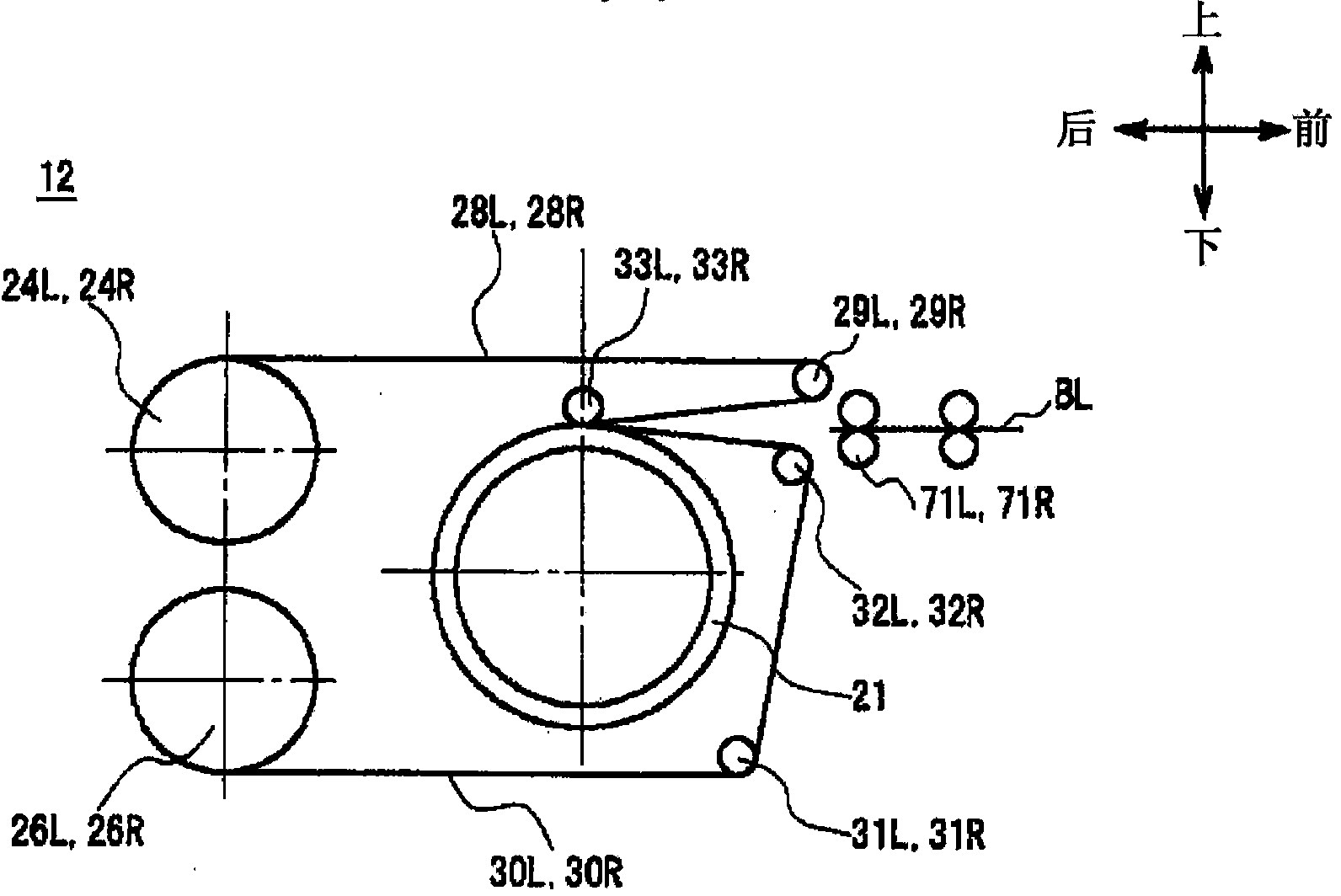
[0199] In addition, in the above-mentioned first and second embodiments, as image 3 As shown, the present invention is applied to the temporary storage units 12 and 80 of the so-called upper take-in method in which banknotes held by two sets of belts that form a pair up and down are wound up from the upper end of the drum and taken in.
[0200] Not limited thereto, the present invention may also be applied to a temporary storage unit of a so-called bottom take-in method in which banknotes held by two sets of belts that form a pair up and down are wound and taken in from the lower end of the drum.
[0201] exist Figure 13 The temporary storage unit 100 of such a downward intake method is shown in . In this temporary storage unit 100 , an upper tape 103 is drawn forward from an upper tape reel 102 arranged on the rear upper side of a cylindrical drum 101 , and the upper tape 103 is stretched in front of the drum 101 . The upper first tape roll 104 is disposed on the upper si...
Embodiment approach 3
[0210] In addition, in the above-mentioned first and second embodiments, two sets of upper and lower pairs of belts are provided in the temporary storage units 12 and 80 , but the present invention is not limited thereto, and three or more sets may be provided.
[0211] Even in the case where three or more sets of upper and lower pairs of belts are installed in this way, it is possible to obtain a It has the same effect as the above-mentioned temporary storage units 12 and 80 .
[0212] [3-4. Other Embodiment 4]
[0213] In addition, in the above-mentioned first and second embodiments, as the torque control unit that controls the torque between each of the tape reels 24L, 24R, 26L, 26R and the reel rotating shafts 22, 23, the torque Limiters 25L, 25R, 27L, 27R. However, the present invention is not limited to this, and other structures that function similarly to torque limiters 25L, 25R, 27L, and 27R may be used instead of torque limiters 25L, 25R, 27L, and 27R.
[0214] [3...
PUM
 Abstract
Description
Claims
Application Information
 - Generate Ideas
- Intellectual Property
- Life Sciences
- Materials
- Tech Scout
- Unparalleled Data Quality
- Higher Quality Content
- 60% Fewer Hallucinations
Browse by: Latest US Patents, China's latest patents, Technical Efficacy Thesaurus, Application Domain, Technology Topic, Popular Technical Reports.
© 2025 PatSnap. All rights reserved.Legal|Privacy policy|Modern Slavery Act Transparency Statement|Sitemap|About US| Contact US: help@patsnap.com