
Microscope slide coordinate system registration

A technology of coordinates and specimens, applied in the field of image processing, can solve the problems of increasing the cost, time-consuming, and difficulties of glass slide manufacturing

Active Publication Date: 2013-12-04
ROCHE DIAGNOSTICS HEMATOLOGY INC
View PDF6 Cites 14 Cited by
  • Summary
  • Abstract
  • Description
  • Claims
  • Application Information

AI Technical Summary

Problems solved by technology

This method is effective but requires special markers printed on the slide, potentially increasing slide manufacturing costs
In addition, the method is time-consuming as it may be necessary to search several locations before locating the fiducial markers in the image
This is especially difficult at high magnifications because the field of view is small compared to imaging sites using lower magnifications

Method used


Image

  • Microscope slide coordinate system registration
  • Microscope slide coordinate system registration
  • Microscope slide coordinate system registration

Examples


Embodiment Construction

[0025] System overview

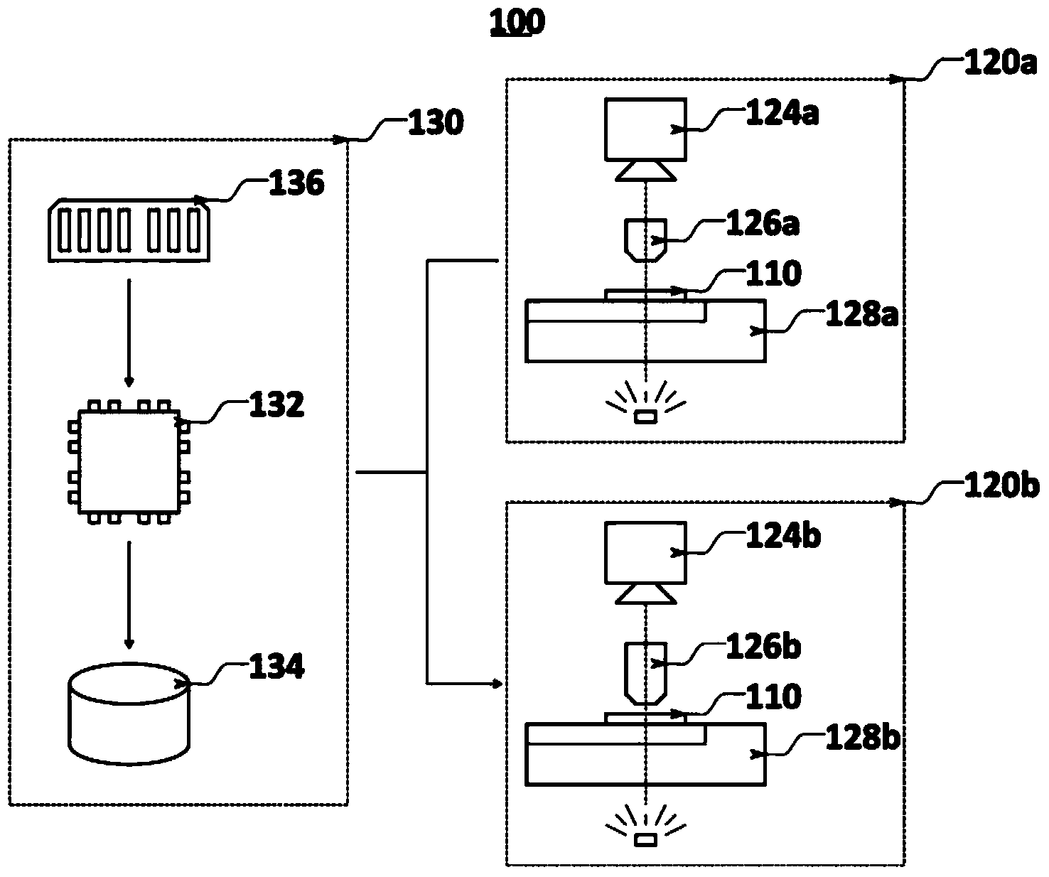
[0026] Figure 1A An example of a biological specimen imaging system 100 controlled by a computer 130 is shown. The computer 130 includes a central processing unit (CPU) 132, a hard drive 134, a memory 136, and other conventionally known hardware components (eg, communication interfaces). Computer 130 is capable of communicating with low magnification imaging site 120a and high magnification imaging site 120b via known communication protocols using standard hardware wiring between the computer and imaging sites. This communication capability allows the computer 130 to command the stages 128a and 128b to move to different (x,y) positions in the horizontal plane, move the objectives 126a and 126b up and down along the vertical axis relative to the surface of the microscope slide 110, and Images captured by cameras 124a and 124b are received.

[0027] The system 100 is capable of capturing and processing images of a biological sample 112 deposited on a ...


PUM


Abstract

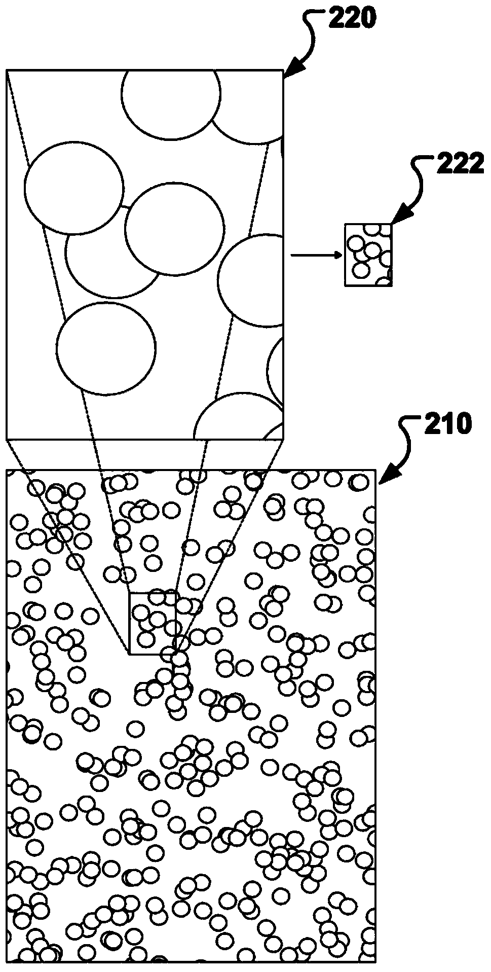
Systems, methods and computer program products for mapping coordinates of various imaging stations are described. In some implementations, cells (e.g.., red blood cells) in a biological specimen (112) can be used for determining the mapping information between the imaging stations (120a, 120b). The use of cells allows a target image (e.g., an image of a sub-region of cells in the biological specimen) taken by one imaging station (120b) to be pattern -matched to a reference image (e.g., an image showing a larger region of cells in the biological specimen that also includes the sub -region) taken by another imaging station (120a). Once the target image is matched to the reference image, point by point correspondence (and therefore coordinates) between the target image and the reference image can be established for computing the coordinate transformation to map the imaging stations.

Description

technical field [0001] The subject matter of this application generally relates to image processing. Background technique [0002] An automated imaging system comprising microscope optics, cameras, a motorized stage, and a computer control system can acquire images of cells from biological specimens deposited on microscope slides. The system can then process these images to identify cells of interest. These cells may need to be revisited later, for example, to obtain higher magnification images of such cells, or to reveal certain cells of interest for manual review. This re-examination often occurs at individual imaging sites. For stage locations that correspond to cells of interest found on the first imaging station, this second imaging station must reposition those exact cells for further examination. [0003] If the coordinate systems of the two imaging stations are the same, the second station can simply move its stage to the stage position reported for a cell on the ...

Claims


Application Information

Patent Timeline
IPC IPC(8): G02B21/36G06T7/00
CPCG06T2207/30024G06T2207/20041G06T2207/10056G02B21/365G06T7/0044G06T7/003G06T7/337G06V20/695G01N33/48G01N33/483G02B21/36G06T7/00G06T7/20
Inventor M.扎尼瑟R.扎尼瑟
Owner ROCHE DIAGNOSTICS HEMATOLOGY INC
Learn More