Microscope slide cover with integrated reservoir

Inactive Publication Date: 2005-12-08
VISION BIOSYST
View PDF12 Cites 50 Cited by
  • Summary
  • Abstract
  • Description
  • Claims
  • Application Information

AI Technical Summary

Benefits of technology

[0023] Preferably a second coating is placed intermediate a first coating

Problems solved by technology

Performing the reactions on the slide can be difficult to automate, as the tissue samples r

Method used


Image

  • Microscope slide cover with integrated reservoir
  • Microscope slide cover with integrated reservoir
  • Microscope slide cover with integrated reservoir

Examples


Embodiment Construction

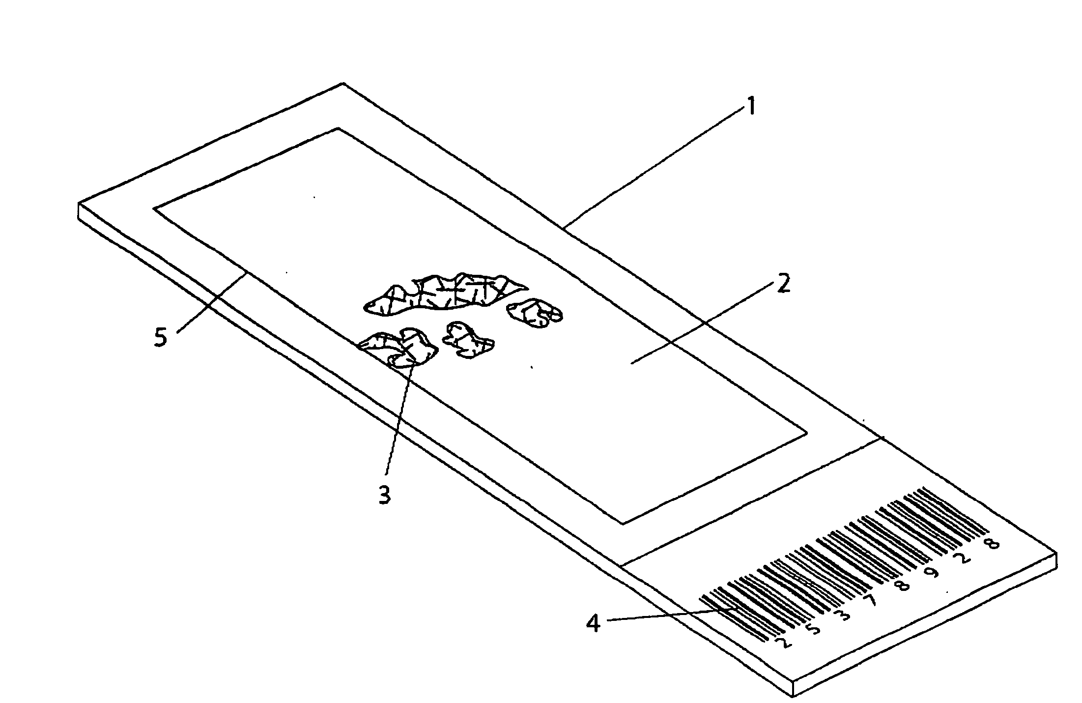
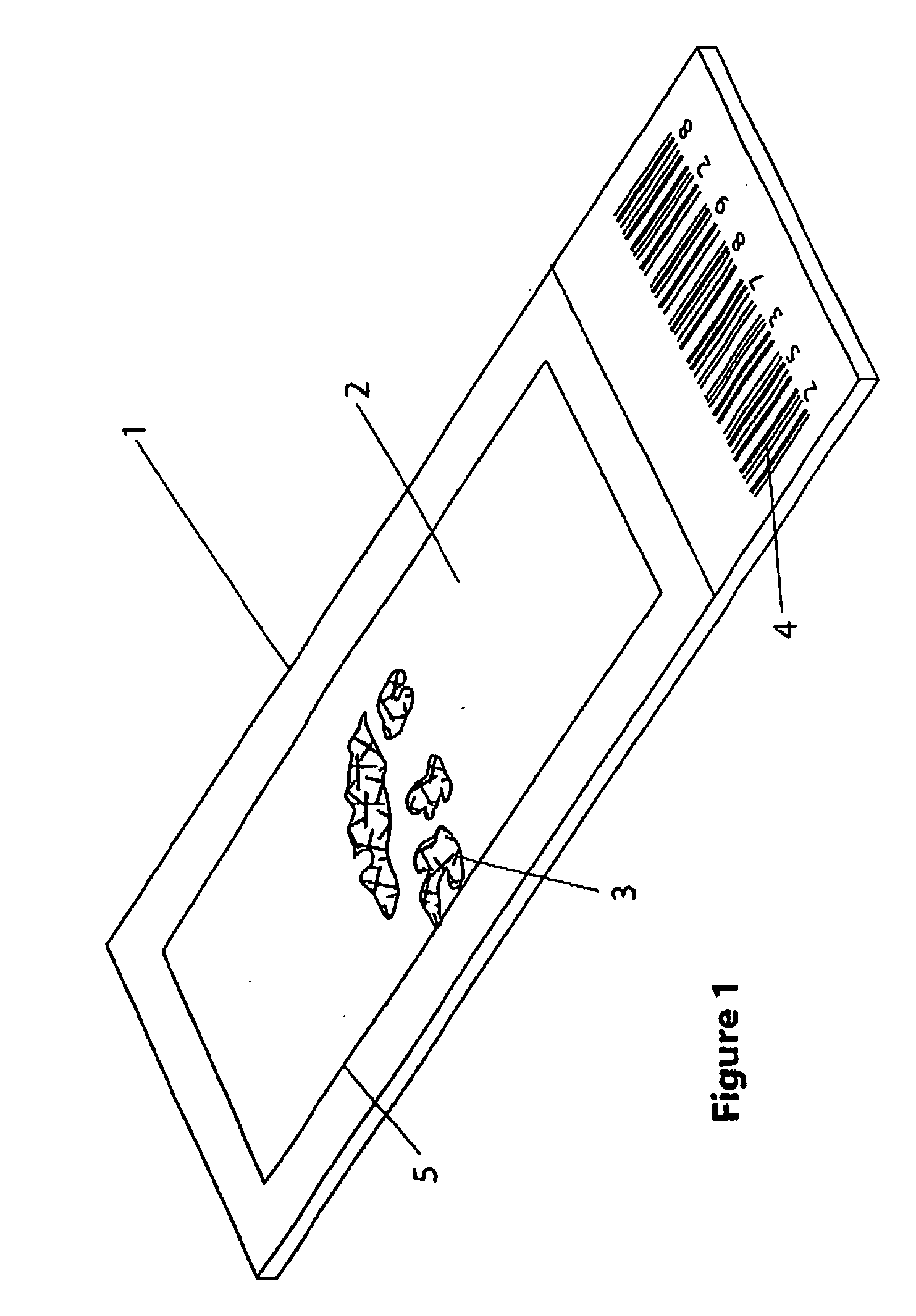
[0050] A microscope slide 1 is shown in FIG. 1 as including an upper surface 2 containing a sample 3. The slide 1 is identified by a unique bar code 4. The sample 3, such as a thinly sliced tissue section, is located on the slide 1 in a sample holding region 5, which needs to be covered by a cover, such as shown in FIG. 2, for subsequent application of test fluids and the like.

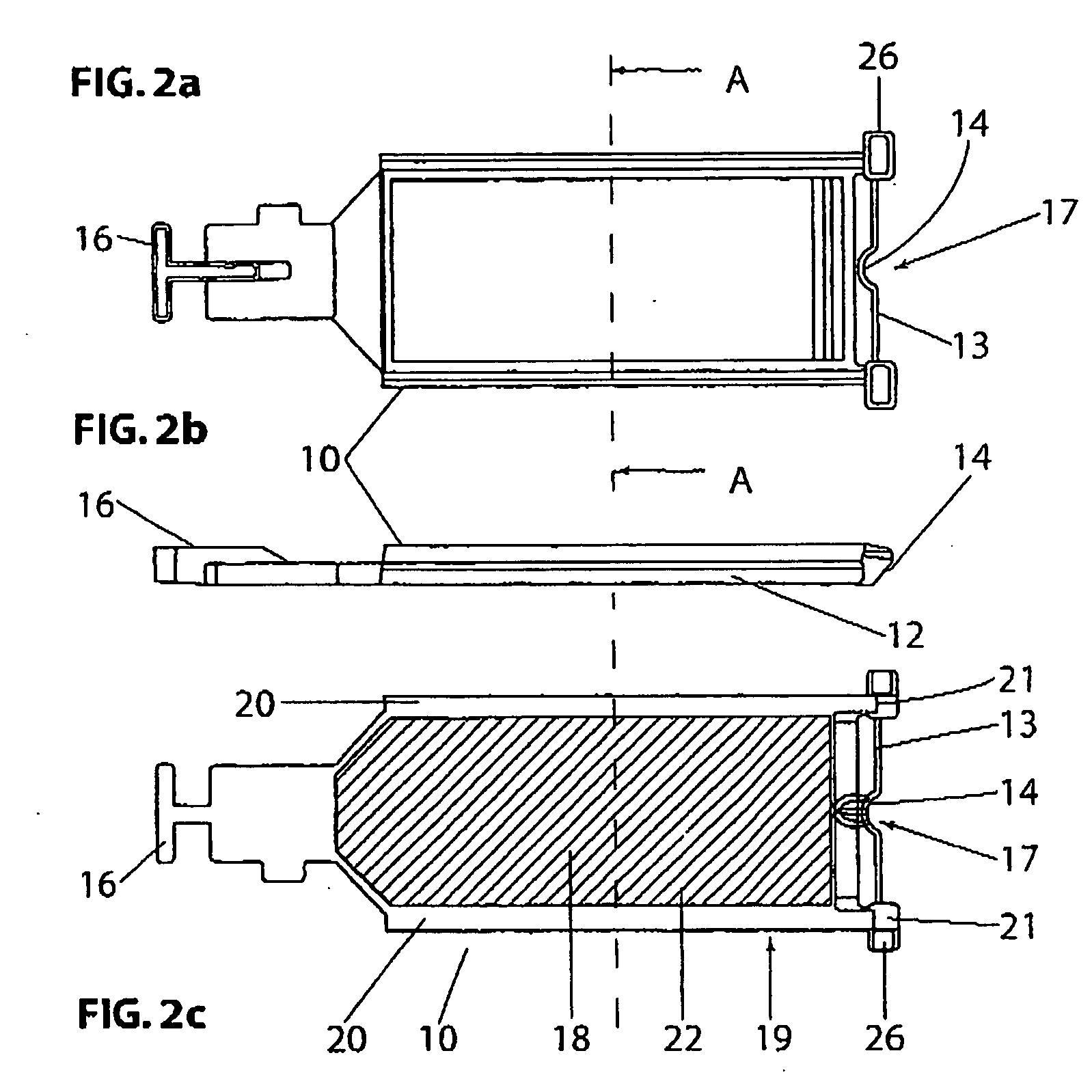
[0051] FIGS. 2 (a)-(c) and FIG. 3 show a cover 10 as having a body 12, a fluid receiving zone 14, a locating means 16 and a cavity 18 on an underside face 19. Surrounding the cavity 18 on two sides is a wall portion 20. At one end of the cover 10, the wall portion 20 joins with legs 21 which extend upwardly and away from the face 19. The legs 21 are spanned by a projection 13 which defines a fluid reservoir 17, between an underside of the projection and the legs 21.

[0052] The cover 10 is shown fitted to a slide 1 in FIGS. 4 and 5. The fluid reservoir 17 is shown roost clearly in FIG. 4 (c) where a detailed v...


PUM


Abstract

A cover (10) for substrate (not shown) including: a body (12) defining a cavity (18), for positioning over the substrate (not shown) to form a reaction chamber (18); and a projection (13) extending from the body (12) to define a fluid reservoir (14), when the cover (10) is fitted to the substrate (not shown), the fluid reservoir (14) being in fluid communication with the cavity (18).

Description

FIELD OF THE INVENTION [0001] The present invention relates to a cover for a substrate, and in one form a cover for use with a microscope slide. BACKGROUND OF THE INVENTION [0002] Microscope slides are commonly used to view samples of material under a microscope. The samples may contain human tissue, and may require treatment such as staining, so that properties of the sample can be identified. Other materials such as DNA, RNA, or proteins may be included on the slide. [0003] It is common for several reactions to be undertaken on a sample on a slide. Once the reactions have taken place the slide may be viewed under a microscope. Performing the reactions on the slide can be difficult to automate, as the tissue samples require careful preparation and certain reactions require carefully controlled environments. SUMMARY OF THE PRESENT INVENTION [0004] In accordance with the present invention, there is provided a cover for a substrate including: [0005] a body defining a cavity, for posit...

Claims


Application Information

Patent Timeline
IPC IPC(8): B01L3/00B01L9/00G01N1/28G01N1/31G01N35/00G02B21/34
CPCB01L3/508B01L9/52B01L2300/021B01L2300/045Y10T436/2575B01L2400/0406G01N2035/00138G02B21/34Y10T436/25B01L2300/0822
Inventor MCLELLAN, ANDREWGORIS, GEORGEHENDERSON, CHESTERMCKINLAY, JONATHAN
Owner VISION BIOSYST
Why Eureka
Try Eureka