Fast clamping mechanism of machine tool

A clamping mechanism and fast technology, applied in the direction of clamping, metal processing machinery parts, supports, etc., can solve the problems of high labor intensity, low work efficiency, and long moving time of the clamping surface, so as to reduce labor intensity and simple structure , The effect of increasing the clamping speed

Inactive Publication Date: 2013-12-11
WUXI YICHEN MOLD TECH
View PDF6 Cites 18 Cited by
  • Summary
  • Abstract
  • Description
  • Claims
  • Application Information

AI Technical Summary

Problems solved by technology

[0003] Aiming at the problems of long moving time of the clamping surface, high labor intensity and low work efficiency caused by the existing clamping mechanism of the machine tool, the invention provides a fast clamping mechanism of the machine tool

Method used


Image

  • Fast clamping mechanism of machine tool
  • Fast clamping mechanism of machine tool

Examples


Embodiment 1

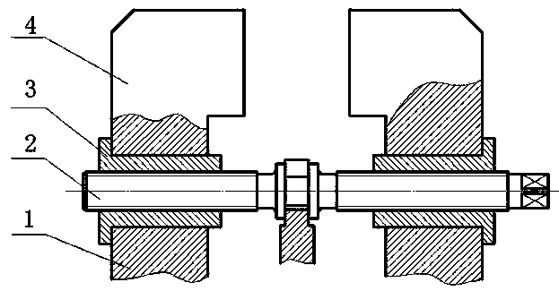
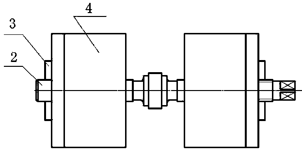
[0019] Such as figure 1 , figure 2 As shown, the fast clamping mechanism of the machine tool includes a slide rail 1, an adjusting screw 2, a moving block 3 and a clamping block 4. The upper end of the slide rail 1 is stuck on the concave edge of the lower end of the moving block 3, and the lower end of the clamping block 4 is pressed On the concave edge of the upper end of the moving block 3 , the adjusting screw 2 is engaged with the moving block 3 . There are two slide rails 1, adjusting screw rods 2, moving blocks 3 and clamping blocks 4; one end of the two adjusting screw rods 2 is connected through a bearing. There is a support bracket at the bottom of the bearing.

[0020] The thread at the left end of the adjusting screw 2 is left-handed, the thread at the right end is right-handed, the thread at the meshing place of the left end of the moving block 3 and the regulating screw 2 is left-handed, and the thread at the meshing place of the right end and the regulating s...

Embodiment 2

[0022] Such as figure 1 , figure 2 As shown, the fast clamping mechanism of the machine tool includes a slide rail 1, an adjusting screw 2, a moving block 3 and a clamping block 4. The upper end of the slide rail 1 is stuck on the concave edge of the lower end of the moving block 3, and the lower end of the clamping block 4 is pressed On the concave edge of the upper end of the moving block 3 , the adjusting screw 2 is engaged with the moving block 3 . There are two slide rails 1, adjusting screw rods 2, moving blocks 3 and clamping blocks 4; one end of the two adjusting screw rods 2 is connected through a bearing.

[0023] The thread at the left end of the adjusting screw 2 is right-handed, the thread at the right end is left-handed, the thread at the meshing place of the left end of the moving block 3 and the regulating screw 2 is right-handed, and the thread at the meshing place of the right end and the regulating screw 2 is left-handed.


PUM


Abstract

The invention discloses a fast clamping mechanism of a machine tool, and belongs to the field of machine tool clamps. The fast clamping mechanism comprises a sliding rail, an adjusting screw rod, a movable block and a clamping block, wherein the upper end of the sliding rail is clamped on the concave edge of the lower end of the movable block, the lower end of the clamping block is pressed on a concave edge of the upper end of the movable block, and the adjusting screw rod is meshed with the movable block. The fast clamping mechanism solves the problems that an existing machine tool clamping mechanism is long in clamping face moving time, large in labor intensity and low in work efficiency, and has the advantages of being simple in structure, reasonable in design and easy to manufacture.

Description

technical field [0001] The invention belongs to the field of machine tool clamps, and more specifically relates to a clamping mechanism for quick clamping of clamps. Background technique [0002] In the machinery manufacturing industry, lathes are widely used to process various parts. When processing parts, the problem of clamping and positioning is involved. At present, when the existing clamps are working, one clamping surface is fixed, and then the other clamping surface is moved to achieve clamping. In this way, due to the one-way movement of a single clamping surface, especially in the frequent clamping and loosening process, it takes a lot of time, increases labor intensity, and reduces work efficiency. In view of the existing problems, it is necessary to design a mechanism for fast clamping of machine tool fixtures to shorten the moving time of the clamping surface, reduce labor intensity and improve work efficiency. Contents of the invention [0003] Aiming at th...

Claims


Application Information

Patent Timeline
Patent Type & Authority Applications(China)
IPC IPC(8): B23Q3/06
Inventor 钱根来李康魏鑫夏守忠陈微霞丁亭
Owner WUXI YICHEN MOLD TECH
Why Eureka
Try Eureka