Automatic polishing device for knuckle bearing

A kind of joint bearing and automatic polishing technology, which is applied in the direction of grinding drive device, surface polishing machine tool, grinding/polishing equipment, etc., can solve the problems of no polishing device and low processing efficiency, so as to reduce labor intensity and high processing efficiency , easy-to-use effects

Pending Publication Date: 2022-04-15
浙江威尔轴承工业有限公司
View PDF0 Cites 1 Cited by
  • Summary
  • Abstract
  • Description
  • Claims
  • Application Information

AI Technical Summary

Problems solved by technology

Due to the irregular shape of the rod end joint bearing, there is no special polishing device, and the processing efficiency is low

Method used


Image

  • Automatic polishing device for knuckle bearing
  • Automatic polishing device for knuckle bearing
  • Automatic polishing device for knuckle bearing

Examples


Embodiment Construction

[0026] The present invention will be further described below in conjunction with the accompanying drawings:

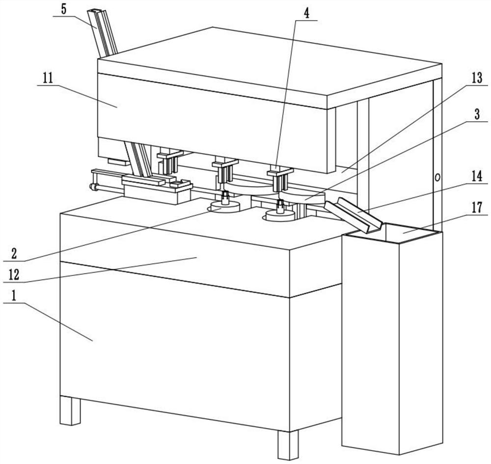
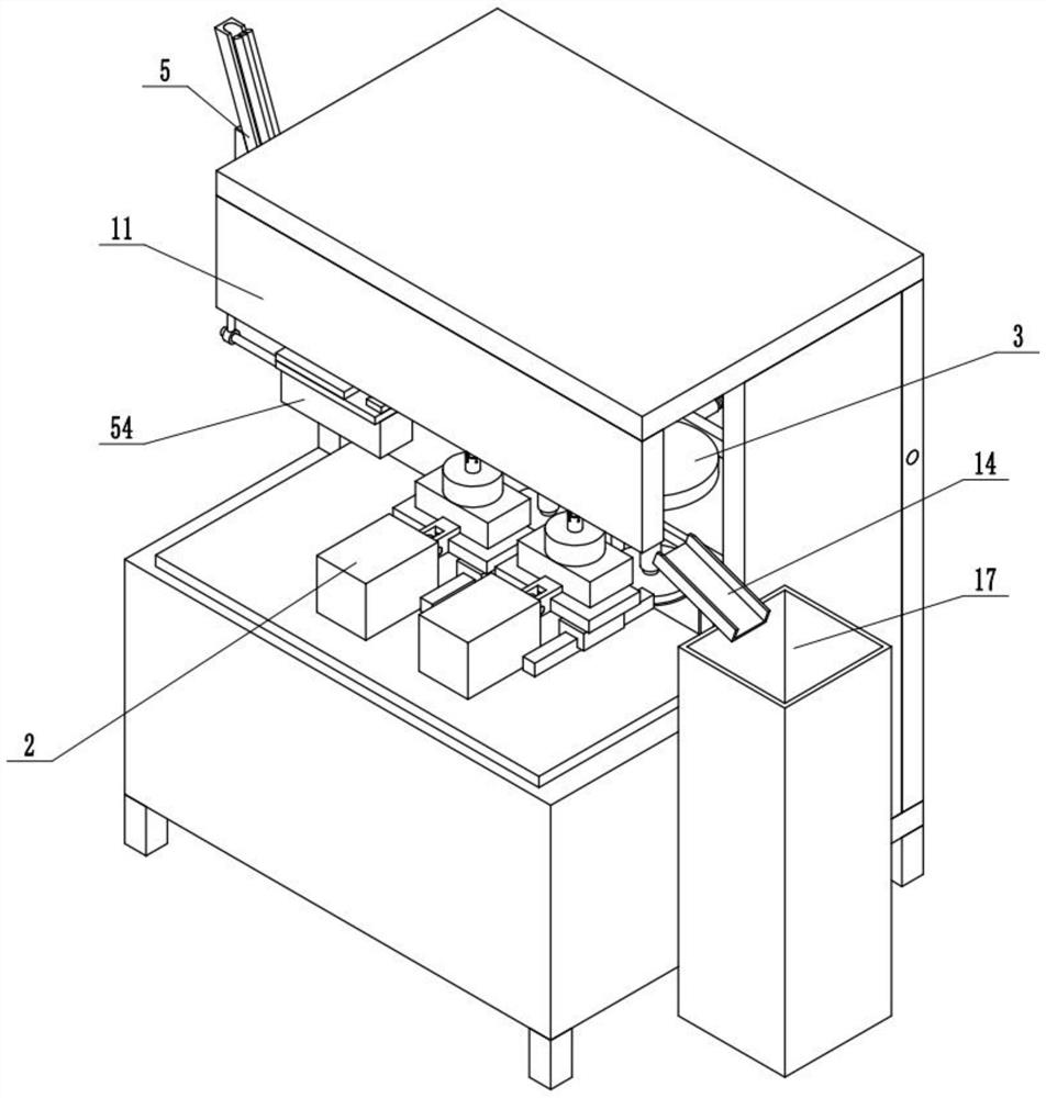
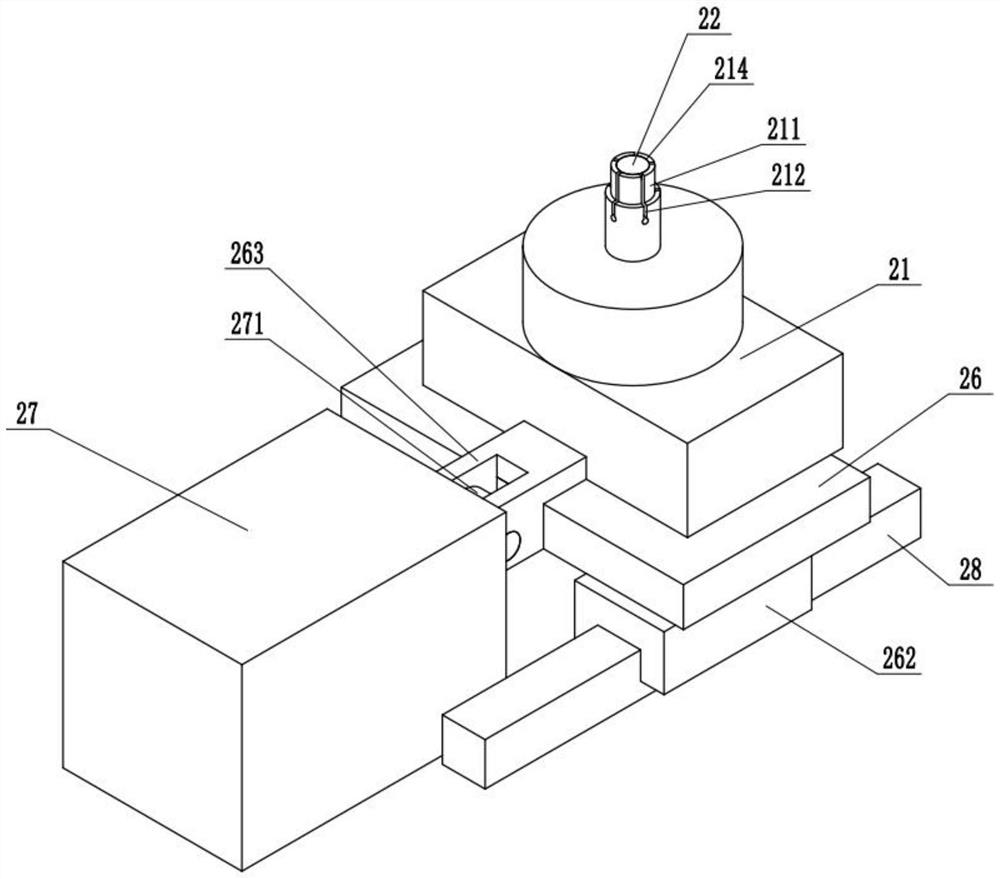
[0027] like Figure 1-4Shown: an automatic polishing device for a spherical plain bearing in this embodiment includes a housing 1, a locking mechanism 2 mounted on the upper end of the housing 1, a polishing mechanism 3 mounted on the rear end of the locking mechanism 2, and the locking mechanism 2. It includes a working cylinder 27 installed on the upper end of the casing 1. The rear end of the working cylinder 27 is connected with a fixing plate 26. The fixing plate 26 is slidably connected to the upper end of the casing 1. The upper end of the fixing plate 26 is fixedly connected with a rotating cylinder 21. The upper end of the rotating cylinder 21 A locking rod 211 is installed, a number of locking grooves 212 are opened on the locking rod 211, and a sliding hole 214 is opened on the locking rod 211, and a locking block 22 is slidably connected in the sliding hole...


PUM


Abstract

The automatic polishing device comprises a shell, a locking mechanism and a polishing mechanism, the locking mechanism comprises a working air cylinder installed at the upper end of the shell, the rear end of the working air cylinder is connected with a fixing plate, the fixing plate is slidably connected to the upper end of the shell, and the upper end of the fixing plate is fixedly connected with a rotating air cylinder; a locking rod is installed at the upper end of the rotating air cylinder, a plurality of locking grooves are formed in the locking rod, a big-end-up sliding hole is formed in the locking rod, a locking block is connected into the sliding hole in a sliding mode, the locking block is in a big-end-up circular truncated cone shape, a connecting rod is fixedly connected to the lower end of the locking block, a pull rod is installed at the lower end of the connecting rod, and a bearing is installed on the outer side of the lower end of the pull rod. The polishing mechanism comprises a polishing wheel, the polishing wheel is located at the rear end of a locking rod and corresponds to the locking rod, a polishing motor is installed at the lower end of the polishing wheel, the machining efficiency is high, and use is convenient and fast.

Description

technical field [0001] The present invention relates to a polishing device, in particular to an automatic polishing device for a joint bearing. Background technique [0002] The spherical plain bearing is a spherical sliding bearing, and the basic type is composed of inner and outer rings with spherical sliding spherical contact surfaces. The spherical plain bearing is mainly composed of an inner ring with an outer spherical surface and an outer ring with an inner spherical surface, which can bear a large load. According to its different types and structures, it can bear radial load, axial load or combined radial and axial load at the same time. Rod end joint bearing is a joint bearing with a rod end or mounted on the rod end, which belongs to a category of joint bearings. Due to the irregular shape of the rod end, there is no special polishing device, and the processing efficiency is low. SUMMARY OF THE INVENTION [0003] The present invention aims to solve the above-m...

Claims


Application Information

Patent Timeline
Patent Type & Authority Applications(China)
IPC IPC(8): B24B29/02B24B41/00B24B41/04B24B41/06B24B47/12B24B47/22
Inventor 黄锡伟
Owner 浙江威尔轴承工业有限公司
Why Eureka
Try Eureka