L-type impact air flow attenuator

A technology of attenuator and airflow, applied in the direction of pipes/pipe joints/pipe fittings, mechanical equipment, pipe components, etc., can solve problems such as shock and vibration, achieve the effects of dissipating energy, reducing costs, and eliminating excessive resistance

Inactive Publication Date: 2013-12-11
XI AN JIAOTONG UNIV
View PDF6 Cites 3 Cited by
  • Summary
  • Abstract
  • Description
  • Claims
  • Application Information

AI Technical Summary

Problems solved by technology

[0003] The purpose of the present invention is to solve the problem of shock vibration caused by the air discharge pipeline on the large and medium-sized high-pressure gas storage tanks, and to provide an L-shaped shock flow for the discharge pipeline with a pipe diversion outside the outlet of the gas storage tank safety valve Attenuator

Method used


Image

  • L-type impact air flow attenuator

Examples


Embodiment Construction

[0016] Below in conjunction with accompanying drawing, the present invention is described in further detail:

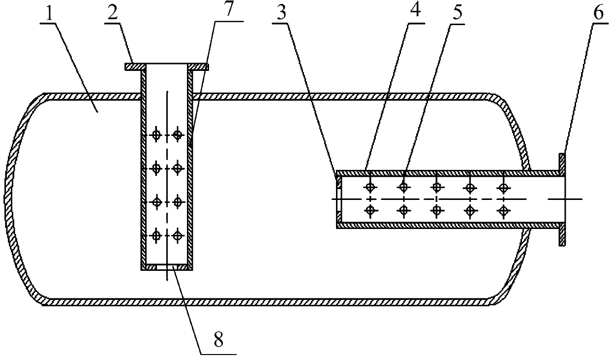
[0017] see figure 1 , the present invention comprises an airflow buffer chamber 1, an air inlet pipe 7 and an air outlet pipe 4 communicating with the inner cavity of the airflow buffer chamber 1 are installed on the airflow buffer chamber 1, and the length of the airflow buffer chamber 1 is the inner diameter of the air inlet pipe 7 or the air outlet pipe 4 The width is 10 to 14 times of that of the inlet pipe 7 or the inner diameter of the outlet pipe 4; The diameter of 5 is 1 / 5~1 / 4 of the internal diameter of air inlet pipe 7 or air outlet pipe 4; The rear end extends into the inside of the airflow buffer chamber 1 from the side of the airflow buffer chamber 1, and the rear end surface of the air inlet pipe 7 is provided with an air inlet orifice 8; The connected air outlet is connected to the flange 6, and the rear end of the air outlet pipe 4 extends into the i...


PUM


Abstract

The invention discloses an L-type impact air flow attenuator which comprises an air flow buffer cavity. An air inlet pipe and an air outlet pipe are installed on the air flow buffer cavity, wherein the air inlet pipe and the air outlet pipe are communicated with a cavity body inside the air flow buffer cavity, the direction changing position of an evacuation pipeline is communicated with the air outlet pipe through the air inlet pipe on the air flow buffer cavity, the air inlet pipe is perpendicular to the air outlet pipe, and L-type layout is arranged inside the air flow buffer cavity. According to the L-type impact air flow attenuator, the characteristics of impact air flow and the evacuation pipeline are comprehensively considered, the basic principles of an interference type air flow buffer, a perforated plate and a hole plate acoustic filter are fused, and the characteristics of the flow exhaust requirements and of the evacuation pipeline and the small installation site of the attenuator are comprehensively considered. For the evacuation pipeline with pipeline steering at the position of an outlet in a security valve, the L-type impact air flow attenuator achieves the effects of dissipating the impact air flow energy, reducing the pipeline coupling, and ensuring the gas exhaust flow requirements to the greatest extent by arranging the air flow buffer cavity and communicating the direction changing position of the evacuation pipeline by the air inlet pipe and the air outlet pipe of the air flow buffer cavity.

Description

technical field [0001] The invention belongs to the field of safety assurance of large and medium-sized gas storage tanks in industries such as petroleum, chemical industry, and energy, and specifically relates to an L-shaped impact air flow attenuator. Background technique [0002] Large and medium-sized high-pressure gas storage tanks are widely used in petroleum, chemical, energy and other industries as pressure vessel equipment for storing gas. The venting pipeline is a key safety measure for this type of gas storage tank. Its function is to quickly discharge the high-pressure airflow that rushes out after the safety valve is automatically opened when the pressure in the gas storage tank exceeds the limit, so as to reduce the pressure of the gas storage tank to a safe range. The coupling between the high-pressure, high-speed impact airflow discharged from the automatic exhaust valve and the vent pipeline will cause vibration problems in the pipeline, especially at the pi...

Claims


Application Information

Patent Timeline
Patent Type & Authority Applications(China)
IPC IPC(8): F16L55/04
Inventor 白长青陈建全韩省亮
Owner XI AN JIAOTONG UNIV
Why Eureka
Try Eureka