An ammonia solution delivery device

A technology of ammonia solution and ammonia water, which is applied in the direction of gas/liquid distribution and storage, pipeline system, mechanical equipment, etc., can solve the problems of uncontrollable output flow and output pressure of ammonia solution, large floor area, and large device volume, etc., to achieve High degree of integration and automation, small footprint and small volume

Active Publication Date: 2015-12-16
江苏鑫氟天科技有限公司
View PDF5 Cites 0 Cited by
  • Summary
  • Abstract
  • Description
  • Claims
  • Application Information

AI Technical Summary

Problems solved by technology

In the denitrification system, the ammonia solution dilution device is generally located at the height of the boiler. The ammonia solution delivery device currently used not only cannot control the output flow and output pressure of the ammonia solution, but also has a large volume, a large floor area, and low work efficiency.

Method used


Image

  • An ammonia solution delivery device

Examples


Embodiment Construction

[0009] The present invention will be further described below in conjunction with the accompanying drawings and specific embodiments.

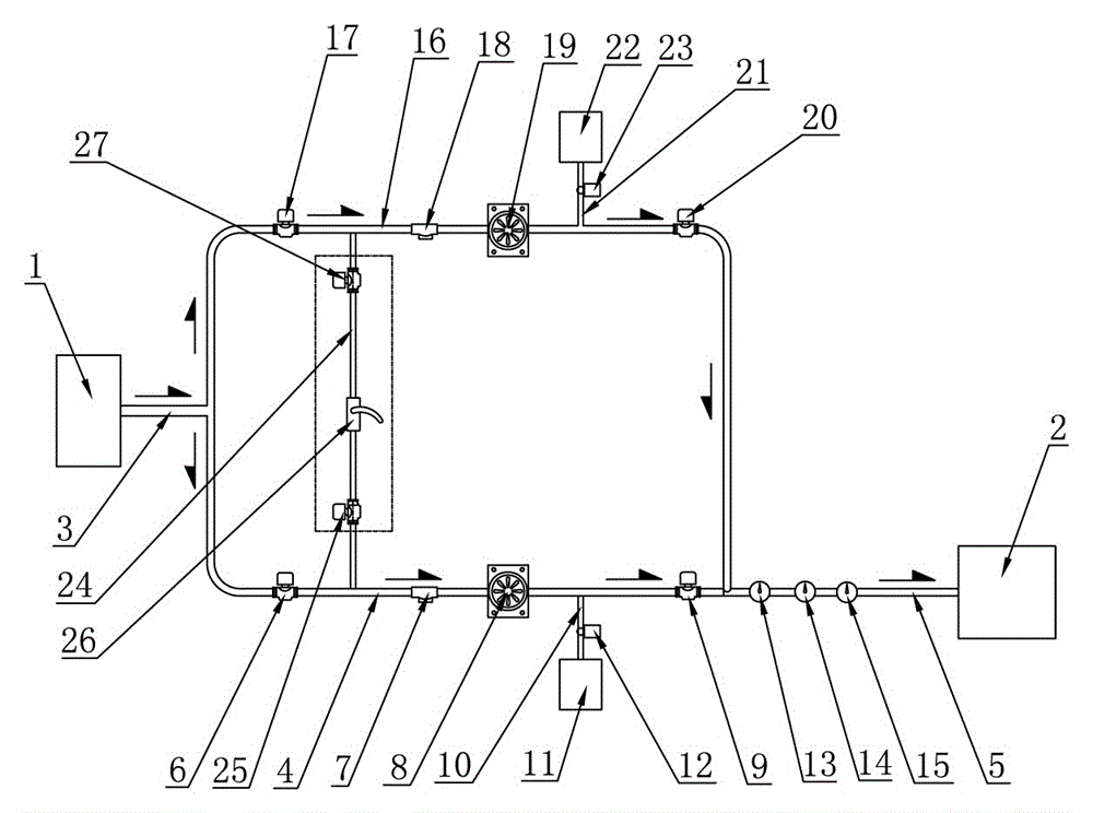
[0010] Such as figure 1 As shown, the described a kind of ammonia solution delivery device includes: the ammonia solution storage tank 1 to be diluted and the ammonia solution dilution device 2, the ammonia solution storage tank 1 to be diluted is connected with the inlet of the first ammonia water inlet main pipe 3, and the first ammonia solution The outlet of the liquid inlet main pipe 3 is connected with the inlet of the first ammonia water inlet liquid branch pipe 4, the outlet of the first ammonia water inlet liquid branch pipe 4 is connected with the entrance of the second ammonia water inlet liquid main pipe 5, and the outlet of the second ammonia water inlet liquid main pipe 5 is connected. It is connected with the ammonia solution diluting device 2; on the first ammonia water inlet branch pipe 4, a first pipeline valve 6, a first filte...


PUM


Abstract

The invention discloses an ammonia solution conveying device which comprises a storage tank of ammonia to be diluted and an ammonia solution diluting device. The storage tank of ammonia to be diluted is communicated with a first ammonia solution liquid inlet header pipe, the first ammonia solution liquid inlet header pipe is communicated with a first ammonia solution liquid inlet branch pipe, the first ammonia solution liquid inlet branch pipe is communicated with a second ammonia liquid inlet header pipe, and the second ammonia solution liquid inlet header pipe is communicated with the ammonia solution diluting device. A first pipeline valve, a first filter, a first frequency conversion multistage centrifugal pump and a second pipeline valve are sequentially arranged on the first ammonia solution liquid inlet branch pipe in the liquid inlet direction of the ammonia solution, the first ammonia liquid inlet branch pipe is communicated with a first flushing water tank through a first flushing water pipeline, and a first control valve is arranged on the first flushing water pipeline; a pipeline temperature monitoring instrument, a pipeline pressure monitoring instrument and a flow meter are sequentially arranged on the second ammonia liquid inlet header pipe in the liquid inlet direction of the ammonia solution. The ammonia solution conveying device has the advantages of being small in size, small in occupied area and capable of controlling the output flow and output pressure of the ammonia solution.

Description

technical field [0001] The invention relates to an ammonia solution conveying device for flue gas denitrification of a coal-fired boiler. Background technique [0002] Ammonia is a commonly used catalytic reducing agent in boiler flue gas denitrification. At present, enterprises generally obtain the ammonia water required for boiler flue gas denitrification by directly purchasing ready-made ammonia water or by pyrolyzing solid urea into ammonia water. The concentration of the ammonia solution obtained by these two methods is generally around 20%. Among them, the ammonia solution with a concentration of about 20% needs to be transported to the ammonia solution dilution device through the ammonia solution delivery device for further dilution, so that the solution concentration of the ammonia solution meets the production requirements. In the denitrification system, the ammonia solution dilution device is generally located at the height of the boiler. The ammonia water deliver...

Claims


Application Information

Patent Timeline
Patent Type & Authority Patents(China)
IPC IPC(8): F17D1/08F17D3/01
Inventor 沈汉斌
Owner 江苏鑫氟天科技有限公司
Why Eureka
Try Eureka