Supercharge Your Innovation With Domain-Expert AI Agents!

Sealed material returning valve with two-way material returning control function

A two-way control and return valve technology, which is applied to the direction of burning fuel in the melting state, lighting and heating equipment, fluidized bed combustion equipment, etc., to achieve the effect of simple structure, not easy to wear, and convenient operation

Active Publication Date: 2013-12-11
SOUTHEAST UNIV
View PDF7 Cites 3 Cited by
  • Summary
  • Abstract
  • Description
  • Claims
  • Application Information

AI Technical Summary

Problems solved by technology

However, when there are two parallel fluidized bed reactors in the system, such as in the chemical looping combustion process or the gasification-combustion polygeneration process, it is necessary to distribute the circulating materials between the two reactors. It is required that the return valve can return materials in both directions at the same time, and the proportion of each direction is controllable within a certain range. Conventional sealed return valves cannot meet this requirement

Method used


Image

  • Sealed material returning valve with two-way material returning control function
  • Sealed material returning valve with two-way material returning control function
  • Sealed material returning valve with two-way material returning control function

Examples


Embodiment 1

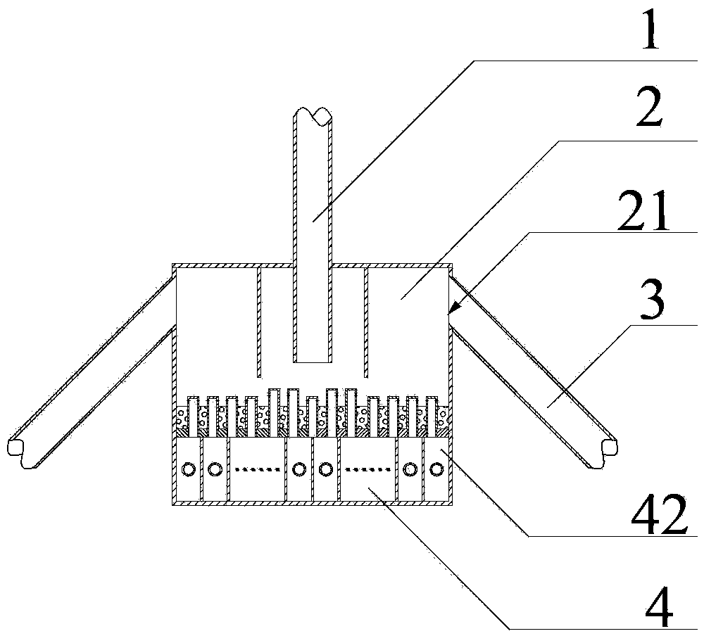
[0020] Such as figure 1 , 2 and 3 show embodiment 1, a sealed return valve that can control the return in two directions, including a descending section 1, two ascending sections 2 and an air chamber 4 at the bottom connected to the first three, and the main body of the return device is a cuboid structure The cross section of the rising section 2 is rectangular, and the return section 3 is connected to the rising section 2 through the overflow port 21, and the overflow ports 21 of the rising section 2 on both sides are equal in height; the air chamber 4 adopts a hood type air distribution plate 45, and It is divided into n independent air chambers 42 by partitions, and each independent air chamber 42 is connected with an air duct 43 which can independently adjust the air volume.

[0021] After the circulating material is separated from the separator, it is sent to the descending section 1 through the standpipe, and under the action of the fluidizing wind from the wind cap 41,...

Embodiment 2

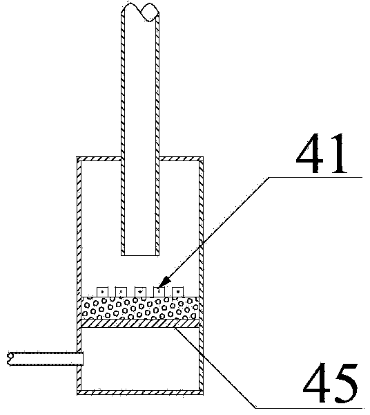
[0023] Such as Figure 4 , 5 Shown is embodiment 2, a sealed return valve that can control the return material in two directions, including a descending section 1, two ascending sections 2 and an air chamber 4 connecting the bottom of the three. The main body of the returner is a cuboid structure; the ascending section The cross section of 2 is rectangular, and the return section 3 is connected to the rising section 2 through the overflow port 21, and the overflow ports 21 of the rising section 2 on both sides are equal in height; the air chamber 4 has n air ducts 43 that can independently adjust the air volume and The air pipe 43 is connected with the horizontal direction at an angle of 30-45 degrees to discharge the slag of the air cap. Each air pipe 43 is connected with m vertical branch pipes 44. The top of the vertical branch pipe 44 is the air cap 41, and the vertical branch pipe 44 and the air duct 43 are flexibly connected with a compensator.

[0024] After the circu...


PUM


Abstract

The invention discloses a sealed material returning valve with a two-way material returning control function for a circulating fluidized bed. Ascending sections (2) which are positioned on the upper part of the sealed material returning valve are respectively arranged on two sides of a descending section (1); every two sections are separated through a separation plate; at least one overflow port (21) is formed in the top side wall of each ascending section (2); each overflow port (21) is connected with a material returning section (3); an air chamber (4) of an air distribution device is formed in the lower part of the sealed material returning valve and is provided with an air-cap-type air distribution plate (45); the lower part of the air distribution plate is partitioned into n independent air chambers (42) through separation plates; each independent air chamber (42) is connected with an air pipe (43) capable of independently controlling opening / closing and air quantity. By virtue of the sealed material returning valve, two-way material returning can be realized, and the material returning quantity of two sides is controlled in a certain range. The sealed material returning valve can be applied to double-fluidized-bed device systems, chemical chain combustion device systems and the like.

Description

technical field [0001] The invention relates to a sealed material return valve capable of bidirectionally controlling material return, which belongs to the intersection field of energy technology and mechanical engineering technology. Background technique [0002] The combustion chamber, separation device and solid material return device are the main components of the circulating fluidized bed boiler that are different from other types of boilers. The basic task of the return device is to stably send the high-temperature solid particles separated by the separator back to the combustion chamber with higher pressure , and prevent the gas from entering the separator. [0003] General flow control devices can be divided into two categories: mechanical valves and non-mechanical valves. The non-mechanical valve does not need any external mechanical force, and only uses gas to push the solid particles to move, so as to realize simple and reliable conveying of solid materials under...

Claims


Application Information

Patent Timeline
IPC IPC(8): F23C10/30
CPCY02E20/34
Inventor 段伦博段元强陈晓平吴新赵长遂
Owner SOUTHEAST UNIV
Features
  • R&D
  • Intellectual Property
  • Life Sciences
  • Materials
  • Tech Scout
  • Unparalleled Data Quality
  • Higher Quality Content
  • 60% Fewer Hallucinations
Learn More