Waste plastic recycling dewatering machine

A waste plastic and dehydrator technology, applied in plastic recycling, recycling technology, dryers and other directions, can solve the problems of seal failure, easy deformation of the casing, long dehydration time, etc., to protect the bearing seat, support reliable, work well reliable results

Inactive Publication Date: 2013-12-11
ZHANGJIAGANG LIANDA MACHINERY
View PDF8 Cites 15 Cited by
  • Summary
  • Abstract
  • Description
  • Claims
  • Application Information

AI Technical Summary

Problems solved by technology

However, the current crusher has the following disadvantages: 1. Since the main shaft is directly installed on the casing through the rotation of the bearing seat, the sealing requirements between the main shaft and the casing are very high, and the main shaft rotates at a high speed, and the casing bears The force of the dehydrator is very large, the casing is easily deformed at the connection with the main shaft, and then the seal will fail to cause water leakage, and the transmission reliability of the bearing seat after the water leakage cannot be guaranteed. Therefore, the structure of the current dehydrator is unreasona

Method used


Image

  • Waste plastic recycling dewatering machine
  • Waste plastic recycling dewatering machine
  • Waste plastic recycling dewatering machine

Examples


Embodiment Construction

[0022] The present invention will be described in further detail below through specific examples.

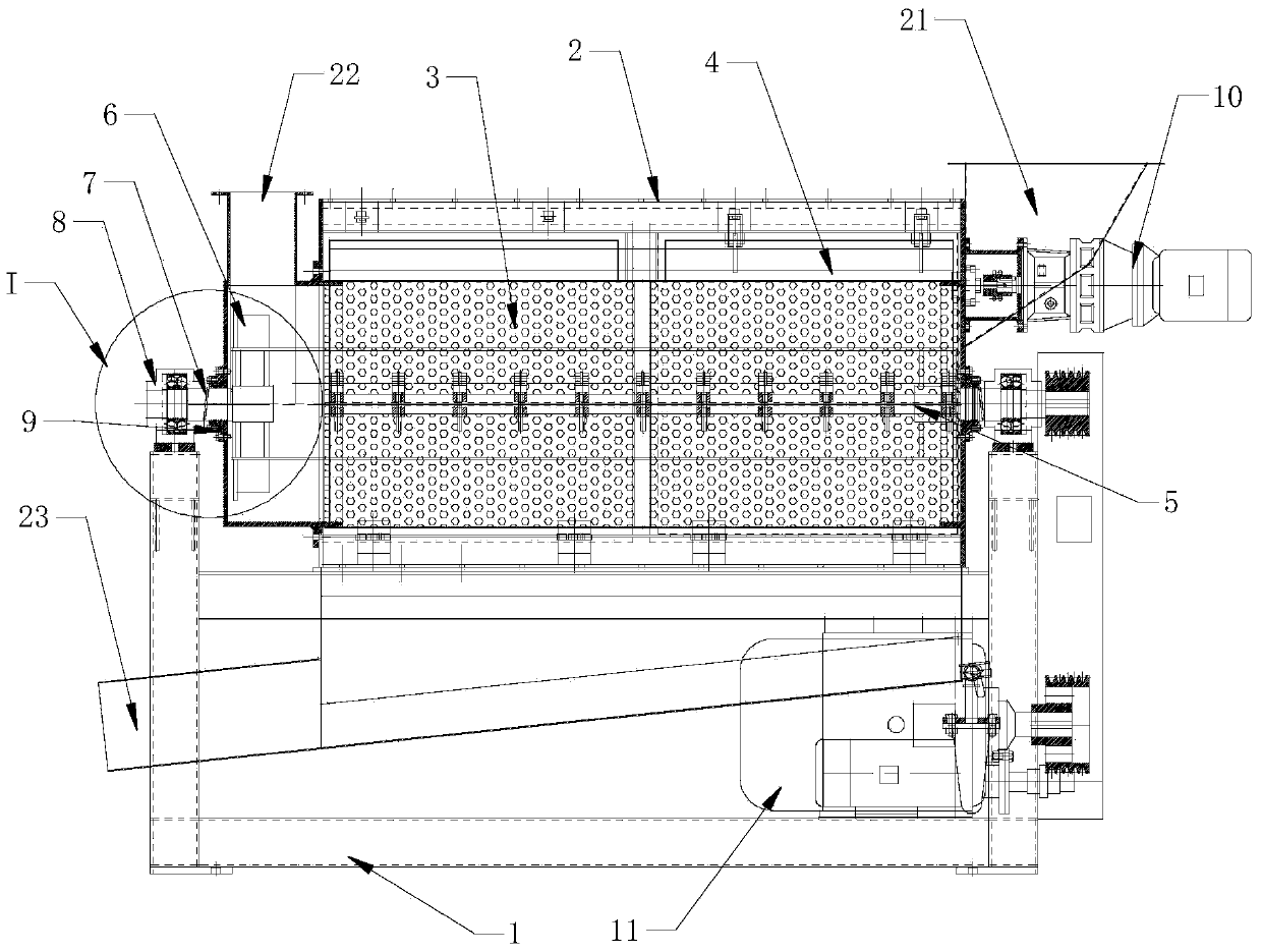
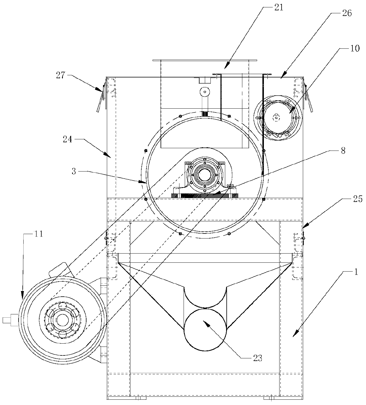
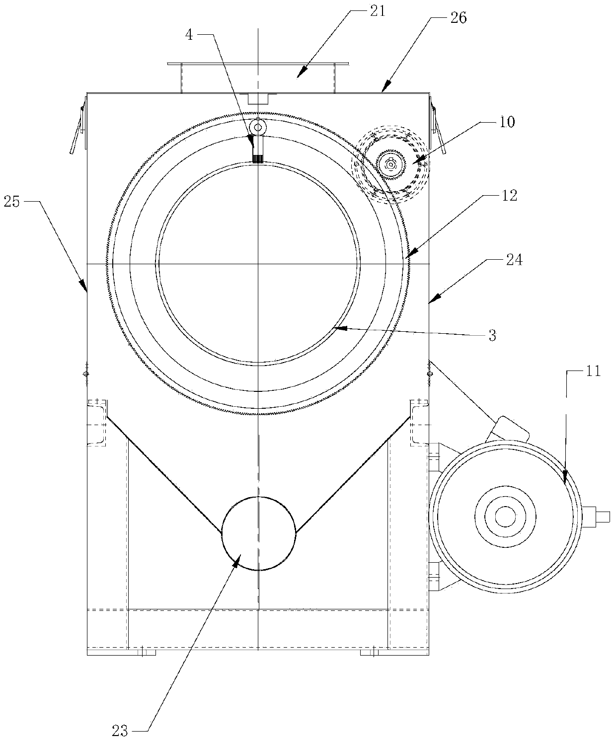
[0023] like figure 1 As shown, a waste plastic recycling dehydrator includes a base 1, a casing 2, a sieve drum and a main shaft 5 with stirring blades, the casing 2 includes a frame and a bottom plate, an upper side cover 26, a front side cover 24 and a rear Side cover 25 and two end plates, two end plates are fixed on the end of frame, and two end plates are provided with the through hole that is convenient to main shaft 5 to pass through, and upper side cover 26 is fixed on the top of frame by bolt, front side The lower ends of the cover 24 and the rear side cover 25 are hinged to the frame, and the upper ends of the front side cover 24 and the rear side cover 25 are locked and fixed with the upper side cover 26 by the buckle structure 27. Like this, the casing 2 is very easy to open. It provides greater convenience for screen replacement, internal maintenance and repairs, e...


PUM


Abstract

The invention discloses a waste plastic recycling dehydrater which comprises a base, a machine shell, a screen drum and a main shaft with mixing blades. The bottom of the machine shell is fixed on the base, the screen drum is fixed in the machine shell, and the main shaft is horizontally installed in the center of the screen drum and penetrates through the screen drum and the machine shell. The two ends of the main shaft are fixed on the base through bearing pedestals, sealing devices are arranged at the connecting positions of the two ends of the main shaft and the machine shell respectively, and the main shaft is driven by a main shaft rotation power device to rotate. One end of the machine shell is provided with a feed port communicated with the interior of the screen drum, the other end of the machine shell is provided with a discharge port communicated with the interior of the screen drum, and a water outlet is formed in the bottom of the machine shell. The dewatering machine is reasonable in stress, and the sealing effect between the main shaft and the machine shell is good. In comparison with an existing structure, the main shaft of the dewatering machine is higher in speed, so that the dewatering effect is better.

Description

technical field [0001] The invention relates to a dehydrator, in particular to a dehydrator used for recycling waste plastics. Background technique [0002] The current plastic dehydrator generally includes a base, a casing, a screen and a main shaft with stirring blades. The casing is fixed on the base, and the two ends of the main shaft are rotated and installed on the casing through bearing seats, and the screen is fixed in the casing. , the blades on the main shaft are within the range of the screen, one end of the casing is provided with a feed port and the other end is provided with a discharge port, the main shaft is driven to rotate by the main shaft rotating power device, and the broken plastic film enters the screen and is agitated by the blades And produce a certain centrifugal force dehydration. However, the current crusher has the following deficiencies: 1. Since the main shaft is directly installed on the casing through the rotation of the bearing seat, the se...

Claims


Application Information

Patent Timeline
IPC IPC(8): F26B11/06F26B5/08F26B25/02F26B25/16B29B17/00B07B1/52
CPCY02W30/62
Inventor 潘学明郑勇
Owner ZHANGJIAGANG LIANDA MACHINERY
Why Eureka
Try Eureka