
A sliding block groove center distance detector and its measuring method

A detector and center distance technology, applied in the direction of measuring devices, instruments, etc., can solve the problems of difficulty in ensuring measurement accuracy, low measurement efficiency, and high labor intensity, and achieve the effects of easy automatic measurement, reduced labor intensity, and no maintenance

Active Publication Date: 2015-09-23
SU CHUNGUANG
View PDF4 Cites 0 Cited by
  • Summary
  • Abstract
  • Description
  • Claims
  • Application Information

AI Technical Summary

Problems solved by technology

[0003] At present, the traditional measurement method for the center distance of the groove of the slider is to place the slider on the measuring plate, use the positioning of the measuring rod in the groove, and use a lever dial gauge to measure the distance from the highest point of the measuring rod to the corresponding surface. The center-to-center distance between the grooves is obtained. This measurement method is not only cumbersome to operate, but also labor-intensive and low-efficiency in measurement. Moreover, the accuracy of measurement is related to the operation method of the operator, which makes it difficult to guarantee the measurement accuracy.

Method used


Image

  • A sliding block groove center distance detector and its measuring method
  • A sliding block groove center distance detector and its measuring method
  • A sliding block groove center distance detector and its measuring method

Examples


Embodiment Construction

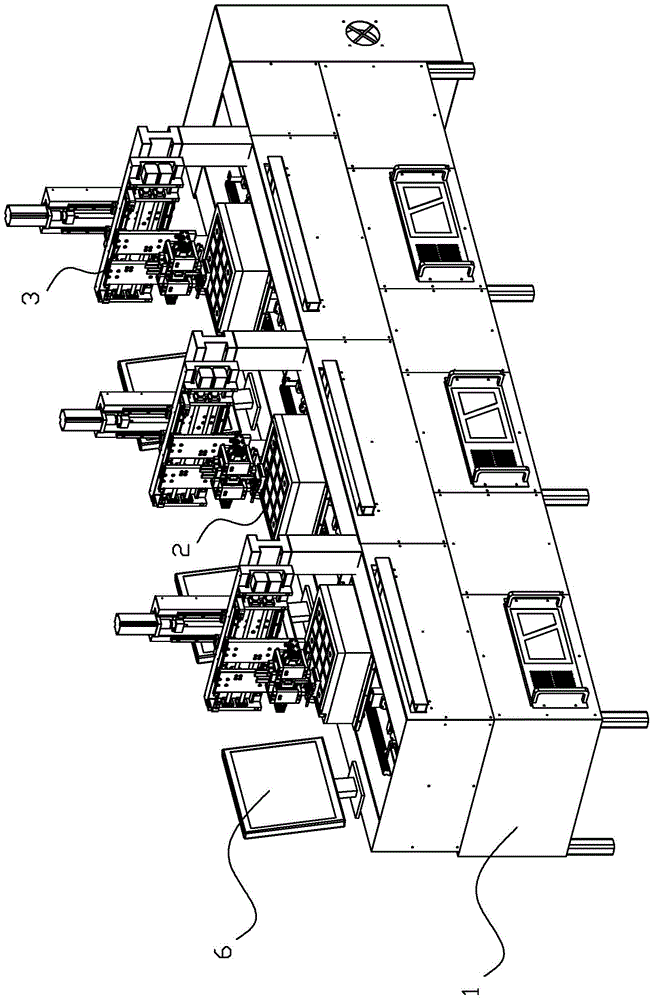
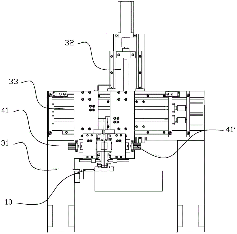
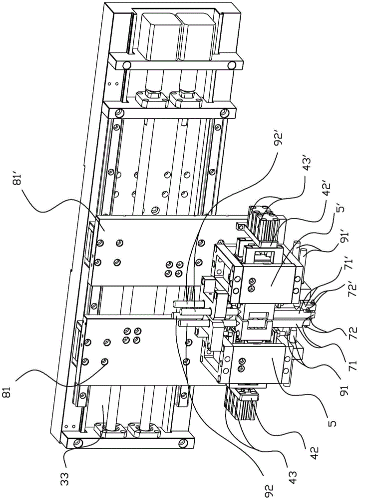
[0030] refer to Figure 1~Figure 5 , a slider groove center distance detector, which includes a frame 1, the frame 1 is slidably installed with a workbench 2 that can move forward and backward for clamping the auxiliary slider of the guide rail, and the frame 1 is fixedly installed with The gantry detection mechanism 3, the gantry detection mechanism 3 includes a gantry 31, the gantry 31 is provided with an up and down moving assembly 32, the up and down moving assembly 32 is equipped with a left and right moving assembly 33, and a left and right moving assembly 33 is slidably installed with a left , right carriage 81,81', left and right carriage 81,81' are respectively equipped with left and right groove detection mechanism 41,41', left and right groove detection mechanism 41,41' include being installed on the left, right The cylinder mounting plate 42,42' on the right carriage 81,81', the left and right cylinder 43,43' are fixed on the cylinder mounting plate 42,42', and the...


PUM


Abstract

The invention discloses a slide block groove center distance detector and a measuring method thereof. The detector comprises a frame; a workbench which can move back and forth and is used for clamping guide pair slide blocks is installed on the frame in a sliding manner; a portal frame detection mechanism is fixedly installed on the frame; the portal frame detection mechanism comprises a portal frame; the portal frame is provided with an up-and-down mobile assembly; the up-and-down mobile assembly is provided with left-and-right mobile assemblies; the left-and-right mobile assemblies are provided with a left carriage and a right carriage; the left carriage and the right carriage are respectively provided with a left groove detection mechanism and a right groove detection mechanism; and besides, horizontal contact probes for detecting the horizontal displacement amounts of a left probe and a right probe, and vertical contact probes for detecting the vertical position amounts of the left probe and the right probe are also arranged. Compared to a conventional detection method which involves manual measuring on a detection flat board, the measuring device provided by the invention can substantially improve the detection precision and detection efficiency, and at the same time greatly reduce the labor intensity of detection personnel.

Description

technical field [0001] The invention relates to a center distance detector, in particular to a slider groove center distance detector and a measuring method thereof. Background technique [0002] After the slider is manufactured, precision measurement is required to ensure that the product meets the acceptance criteria. The most important thing for the slider is to detect the center distance of the groove. At present, the center distance detection mainly has two indicators, namely: the vertical center of the groove Distance and groove horizontal center distance. [0003] At present, the traditional measurement method for the center distance of the groove of the slider is to place the slider on the measuring plate, use the positioning of the measuring rod in the groove, and use a lever dial gauge to measure the distance from the highest point of the measuring rod to the corresponding surface. The center-to-center distance between the grooves is obtained. This measurement met...

Claims


Application Information

Patent Timeline
Patent Type & Authority Patents(China)
IPC IPC(8): G01B21/16
Inventor 叶飞原扬炫召张艳红冯健文
Owner SU CHUNGUANG
Learn More