
Single-channel radio direction finding system

A radio direction finding and single-channel technology, applied in the field of antenna engineering, can solve the problems of direction finding failure, high cost, and phase relationship confusion, and achieve the effect of simple structure and low cost

Active Publication Date: 2013-12-11
SHANGHAI JIAO TONG UNIV
View PDF3 Cites 19 Cited by
  • Summary
  • Abstract
  • Description
  • Claims
  • Application Information

AI Technical Summary

Problems solved by technology

Compared with the single-channel direction-finding system, the direction-finding system with multiple radio frequency channels has the disadvantages of complex hardware structure and high cost. At the same time, the amplitude and phase consistency of each radio frequency channel is required to be good, and additional correction equipment is required.
Chinese patent "A single-channel radiolocation and direction-finding system and its direction-finding method" (patent application number: 201010598996.2) proposes a single-channel direction-finding method, which uses a switch to switch between antenna units distributed around the circumference. The phase relationship of radio signals received on adjacent antenna units is used to perform direction finding, but this direction finding method requires that only one radio signal is incident in a direction finding cycle
When multiple radio signals are incident at the same time, the resulting phase relationship is confused, causing direction finding failure

Method used


Image

  • Single-channel radio direction finding system
  • Single-channel radio direction finding system
  • Single-channel radio direction finding system

Examples


Embodiment Construction

[0041] The following is a detailed description of the embodiments of the present invention: this embodiment is implemented on the premise of the technical solution of the present invention, and provides detailed implementation methods and specific operation processes. It should be noted that those skilled in the art can make several modifications and improvements without departing from the concept of the present invention, and these all belong to the protection scope of the present invention.

[0042] Please also see Figure 1 to Figure 5 .

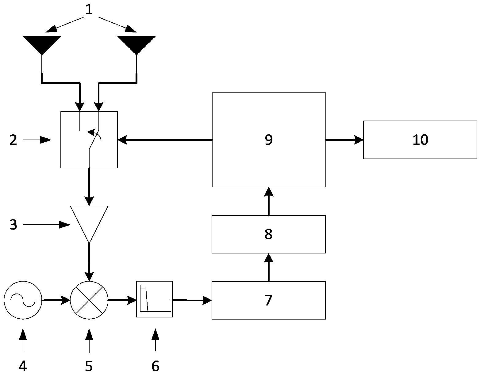
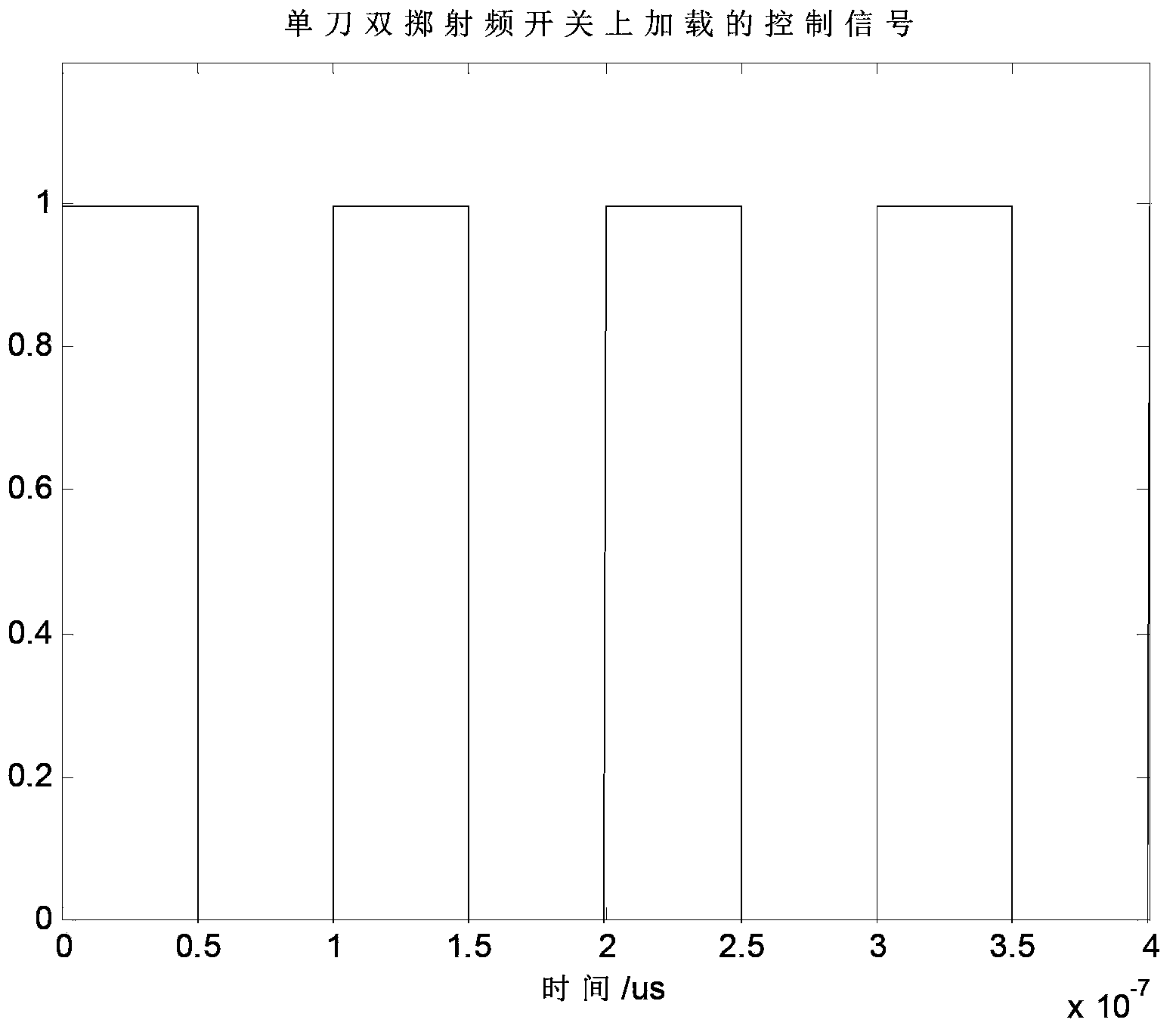
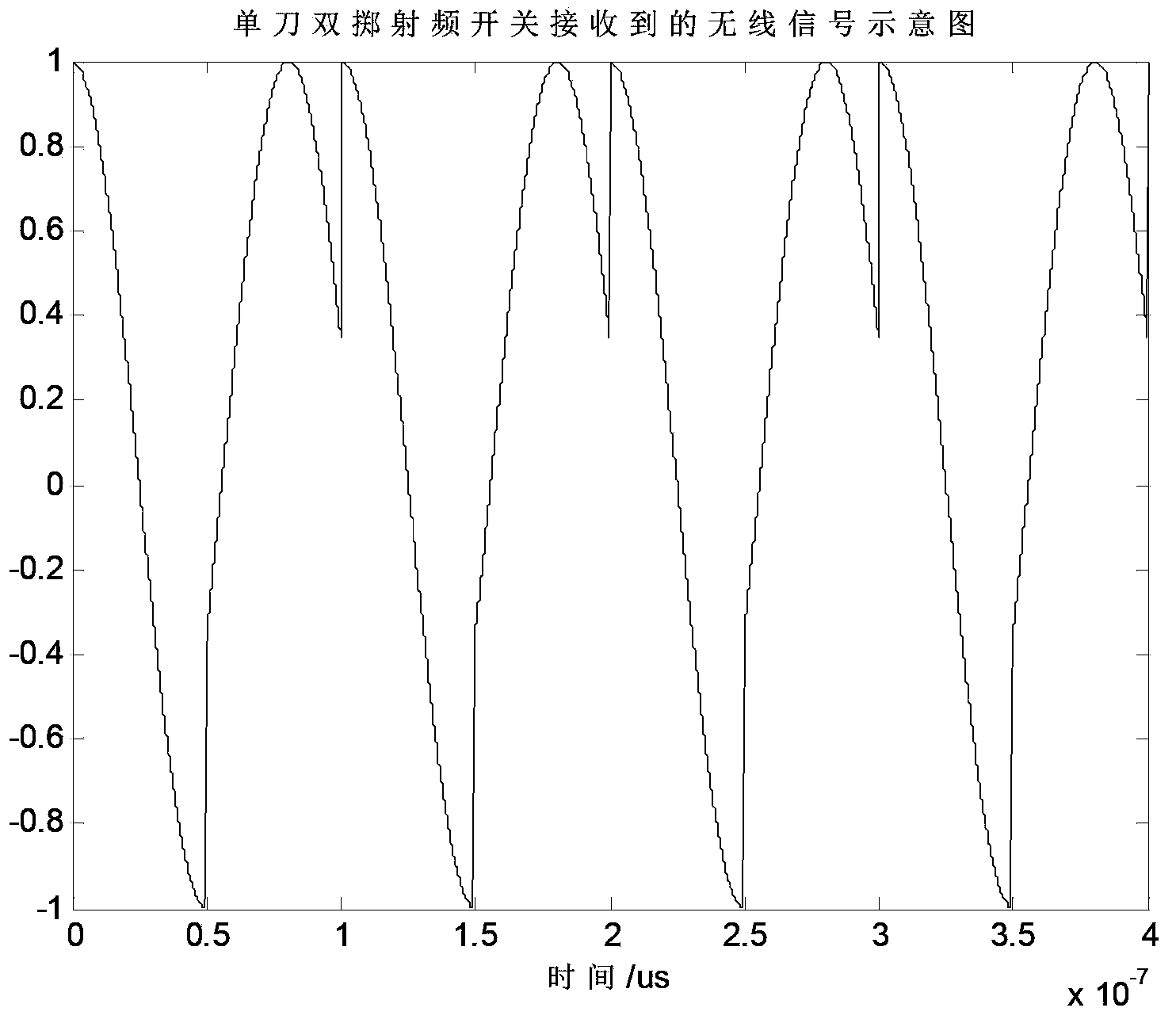
[0043] This embodiment provides a single-channel radio direction finding system, including an antenna array 1, a single-pole double-throw radio frequency switch module 2, a receiving radio frequency channel, a spectrum analysis module 8, a control module 9 and an output display module 10, the antenna array 1 Connected with the single pole double throw radio frequency switch module 2, the single pole double throw radio frequency switch mo...


PUM


Abstract

The invention discloses a single-channel radio direction finding system. The single-channel radio direction finding system comprises an antenna array, a single-pole double-throw radio frequency switch module, a radio frequency receiving channel, a spectral analysis module, a control module and an output display module, wherein the antenna array is connected with the single-pole double-throw radio frequency switch module, the single-pole double-throw radio frequency switch module is connected with the radio frequency receiving channel, the radio frequency receiving channel is connected with the spectral analysis module, the spectral analysis module is connected with the control module, and the control module is connected with the single-pole double-throw radio frequency switch module and the output display module. The single-channel radio direction finding system is used for solving the problem of radio direction finding in the communication application, the military application and the like, the antenna array which is controlled by a high-speed radio frequency switch and carries out periodic switching is adopted, and measurement of the radio incident direction is achieved through analysis of frequency spectrum components of a received radio signal. The single-channel radio direction finding system is applicable to rapid radio direction finding needing low hardware complexity and low cost.

Description

technical field [0001] The invention relates to the technical field of antenna engineering, in particular to a single-channel radio direction-finding system for realizing radio direction-finding by using a single radio frequency channel. Background technique [0002] Traditional radio direction-finding technology generally consists of antenna arrays, multi-channel receivers and controllers, and output display modules, such as phase interferometers, and direction-finding arrays based on super-resolution spatial spectrum estimation. Compared with the single-channel direction-finding system, the direction-finding system with multiple radio frequency channels has the disadvantages of complex hardware structure and high cost. At the same time, the amplitude and phase consistency of each radio frequency channel is required to be better, and additional correction equipment is required. Chinese patent "A single-channel radiolocation and direction-finding system and its direction-fin...

Claims


Application Information

Patent Timeline
IPC IPC(8): G01S3/46
Inventor 贺冲曹岸杰梁仙灵金荣洪耿军平
Owner SHANGHAI JIAO TONG UNIV
Learn More