
A laser grating positioning system for rail moving equipment

A technology of mobile equipment and positioning system, applied in the direction of control using feedback, can solve the problems of poor positioning accuracy and reliability, high price, and achieve the effect of high positioning accuracy

Active Publication Date: 2016-03-16
广西恒帆智能科技有限公司
View PDF8 Cites 0 Cited by
  • Summary
  • Abstract
  • Description
  • Claims
  • Application Information

AI Technical Summary

Problems solved by technology

[0003] The technical problem to be solved by the present invention is to provide a laser grating positioning system for rail moving equipment to solve the above-mentioned shortcomings of high price, poor positioning accuracy and reliability in the prior art

Method used


Image

  • A laser grating positioning system for rail moving equipment
  • A laser grating positioning system for rail moving equipment
  • A laser grating positioning system for rail moving equipment

Examples


Embodiment 1

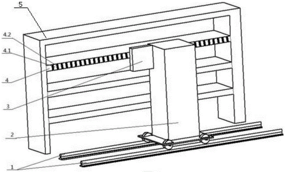
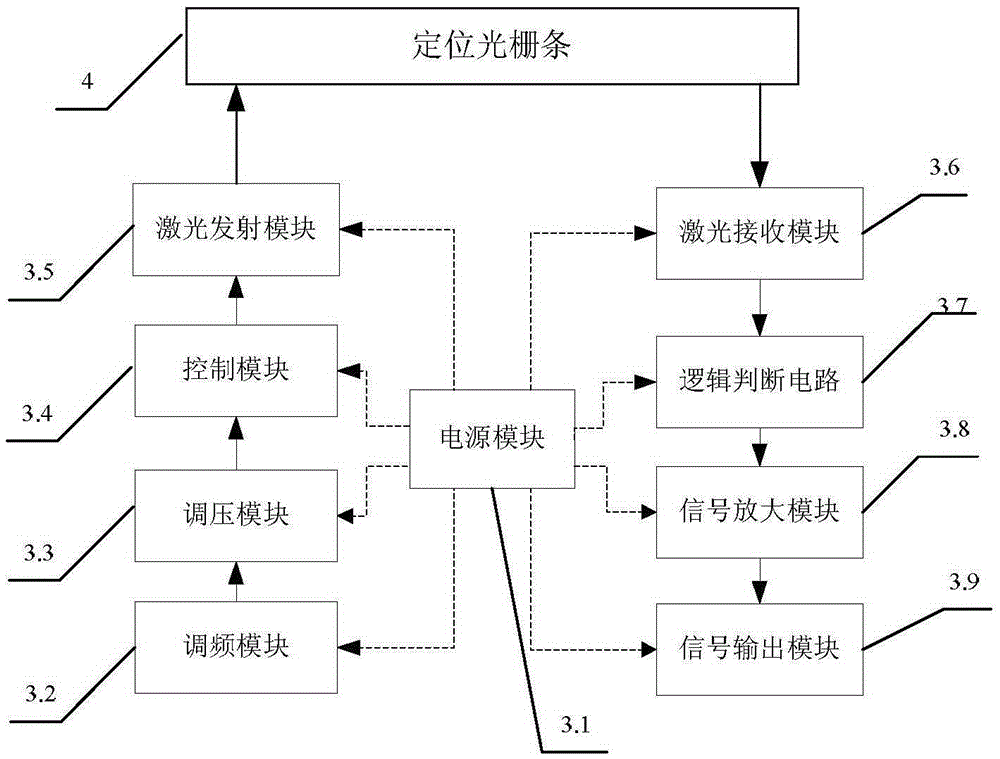
[0037] A laser grating positioning system for rail mobile equipment, including a moving guide rail 1, a mobile device 2, a laser emitting and receiving module 3, and a positioning grating bar 4 (see figure 1 ), the motion guide rail 1 is used to provide the motion constraint and motion trajectory of the mobile device; the bottom of the mobile device 2 is installed on the motion rail and moves left and right along the motion rail; the laser emitting and receiving module 3 is fixed on On the mobile device 2, it is used to emit laser light and receive reflected laser signals; the positioning grating bar 4 is installed on a fixed object frame 5 (such as a shelf, a bookcase and a medicine cabinet, etc.) and form the reflected laser signal.

[0038] The positioning grating strips 4 are alternately arranged in areas I 4.1 and II 4.2 (see figure 2); said area I4.1 is a diffuse reflection area that does not absorb light, and this area I4.1 is coated with a diffuse reflection material...


PUM


Abstract

The invention provides a laser raster locating system for a rail mobile device and relates to a laser locating system. The laser raster locating system for the rail mobile device comprises a movement guide rail (1), the mobile device (2), a laser emitting and receiving module (3) and a locating raster bar (4). The movement guide rail (1) is used for offering movement restraint and a movement trail of the mobile device; the bottom of the mobile device (2) is installed on the movement guide rail and the mobile device (2) moves laterally along the movement guide rail; the laser emitting and receiving module (3) is fixed to the mobile device (2) and used for emitting lasers and receiving reflected laser signals; the locating raster bar (4) is installed on a fixed rack (5) and used for providing the reflected laser signals with different intensities and modes, wherein the fixed rack (5) is used for containing an object to be located. According to the laser raster locating system for the rail mobile device, the locating error is smaller than 2mm, the locating accuracy and the locating reliability are high, the manufacturing cost is low, and the laser raster locating system for the rail mobile device is particularly suitable for the accurate location of the rail mobile device.

Description

technical field [0001] The invention relates to a laser positioning system, in particular to a laser grating precise positioning system for rail moving equipment based on the principles of laser total reflection and diffuse reflection. Background technique [0002] With the development of science and technology and society, a large number of smart mobile devices are emerging, such as smart storage systems, smart library systems and book ATM machine systems. In these systems, the precise positioning technology of manipulators, robotic arms, and stackers is very important, and most of the existing positioning technologies use methods such as laser distance measurement, motion trajectory calculation, and barcode scanning. These existing technologies have the disadvantages of high price, poor positioning accuracy and poor reliability. Contents of the invention [0003] The technical problem to be solved by the present invention is to provide a laser grating positioning system...

Claims


Application Information

Patent Timeline
Patent Type & Authority Patents(China)
IPC IPC(8): G05D3/12
Inventor 向风帆向宇张彦会伍松王镇江
Owner 广西恒帆智能科技有限公司
Learn More