Component transfer device with six-degree-of-freedom regulating function in nuclear fusion environment

A technology of transfer device and degree of freedom, which is applied in the field of nuclear fusion environment, can solve problems such as multi-degree-of-freedom adjustment of parts transfer device, and achieve the effect of ensuring safety and stability

Inactive Publication Date: 2013-12-11
HEFEI INSTITUTES OF PHYSICAL SCIENCE - CHINESE ACAD OF SCI
4 Cites 13 Cited by

AI-Extracted Technical Summary

Problems solved by technology

[0008] The purpose of the present invention is to solve the defect in the prior art that the multi-degree-of-freedom adjustment of the component transfer device in the nuclear fusion environ...

Method used

During actual use, the component transfer device under the nuclear fusion environment is transported to the vicinity of the docking object, and the hydraulic cylinder E203 works to drive the lower supporting plate 120 to move laterally, thereby driving the entire rotating device to move laterally. After the horizontal adjustment is in place, the hydraulic cylinder F204 works to drive the middle support plate 213 to move longitudinally, thereby driving the entire rotating device to move longitudinally. After the longitudinal adjustment is in place, the hydraulic cylinder G207 works to drive the upper supporting plate 307 to rotate on the vertical axis, thereby driving the entire rotating device to rotate on the vertical axis. At this time, the large-scale adjustment between the component transfer device and the docking object in the nuclear fusion environ...

Abstract

The invention relates to a component transfer device with the six-degree-of-freedom regulating function in a nuclear fusion environment. Compared with the prior art, the component transfer device overcomes the defect that multi-degree-of-freedom regulation on component transfer devices in the nuclear fusion environment cannot be achieved. The component transfer device comprises a bracket supporting system and a box body, and further comprises a six-degree-of-freedom regulating system arranged between the bracket supporting system and the box body. The six-degree-of-freedom regulating system comprises a parallel-connected three-degree-of-freedom rotating platform and a superposed three-degree-of-freedom moving platform. The box body is arranged on the parallel-connected three-degree-of-freedom rotating platform, and the superposed three-degree-of-freedom moving platform is arranged on the bracket supporting system. The component transfer device can better guarantee docking regulation with degrees of freedom in all directions on components in the transfer process in the nuclear fusion environment, and guarantee stability, flexibility and safety of the components in the process of using radiant high temperature fuel in the nuclear fusion environment.

Application Domain

Nuclear energy generationThermonuclear fusion reactor

Technology Topic

Image

  • Component transfer device with six-degree-of-freedom regulating function in nuclear fusion environment
  • Component transfer device with six-degree-of-freedom regulating function in nuclear fusion environment
  • Component transfer device with six-degree-of-freedom regulating function in nuclear fusion environment

Examples

  • Experimental program(1)

Example Embodiment

[0030] In order to have a further understanding and understanding of the structural features of the present invention and the achieved effects, a detailed description with preferred examples and drawings is described as follows:
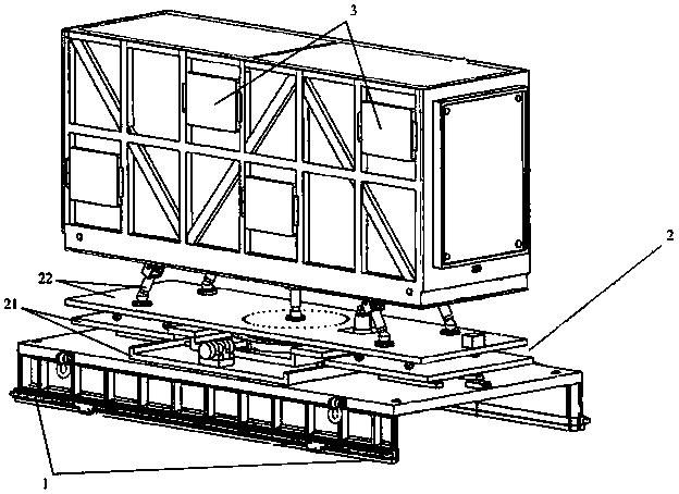
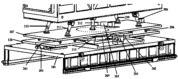
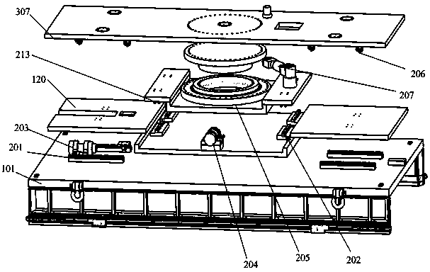
[0031] Such as figure 1 As shown, a component transfer device with six degrees of freedom adjustment function in a nuclear fusion environment according to the present invention includes a bracket support system 1 and a box body 3, and also includes a bracket support system 1 and a box body installed 3, the six-degree-of-freedom adjustment system 2. The six-degree-of-freedom adjustment system 2 includes a parallel three-degree-of-freedom rotating platform 22 and a superimposed three-degree-of-freedom mobile platform 21. The superimposed three-degree-of-freedom mobile platform 21 realizes movement along the horizontal axis and along the vertical axis The functions of moving and rotating around the vertical axis, the parallel three-degree-of-freedom rotating platform 22 realizes the functions of rotating around the horizontal axis, rotating around the vertical axis, and moving along the vertical axis, which are combined into a six-degree-of-freedom adjustment system 2. The car body 3 is installed on the parallel three-degree-of-freedom rotating platform 22, and the superimposed three-degree-of-freedom mobile platform 21 is installed on the bracket support system 1 to form a complete component transfer device with six degrees of freedom adjustment function in a nuclear fusion environment.
[0032] Such as figure 2 with image 3 As shown, the parallel three-degree-of-freedom rotating platform 22 of the present invention includes an upper pallet 307. Above the upper pallet 307, a hydraulic cylinder A208, hydraulic cylinder B209, hydraulic cylinder C210, hydraulic cylinder D211 and The box body 3 is fixedly installed. Hydraulic cylinder A208, hydraulic cylinder B209, hydraulic cylinder C210, and hydraulic cylinder D211 are arranged symmetrically with four-sided prisms, which can be hydraulically adjusted up and down respectively, and can realize the functions of rotating around the horizontal axis, rotating around the vertical axis and moving along the vertical axis in a small range. The three-degree rotation of the parallel three-degree-of-freedom rotating platform 22 is realized in a small range, and is used as a minor adjustment to ensure the parallel and seamless connection between the transfer device and the docking object. The hydraulic cylinder A208, the hydraulic cylinder B209, the hydraulic cylinder C210, the hydraulic cylinder D211 and the upper support plate 307 are connected by ball glue, and a cross hinge is adopted between the bottom surface of the box body 3. In order to support and strengthen the device and better facilitate the long-term use of the device, it can include a hydraulic drive rod 212. The lower part of the hydraulic drive rod 212 is fixedly installed in the upper middle of the upper support plate 307, and installed in the hydraulic cylinder A208, hydraulic cylinder B209, and hydraulic cylinder. The central part of the four-sided prism formed by C210 and hydraulic cylinder D211 adopts a fixed link, and the upper part of the hydraulic drive rod 212 is installed under the car body 3 with a cross hinge. The superimposed three-degree-of-freedom mobile platform 21 includes a middle pallet 213 and a lower pallet 120. The lower middle of the upper pallet 307 is connected to the middle pallet 213 through the turntable bearing unit 205. The pallet 213 is equipped with a hydraulic cylinder E207, which passes through the hydraulic cylinder E207. It passes over the upper support plate 307 and is fixedly installed above the upper support plate 307. The turntable bearing unit 205 realizes rotation around the vertical axis, and the turntable bearing unit 205 is installed between the middle support plate 213 and the upper support plate 307. The hydraulic cylinder E207 passes through the through hole in the middle of the upper support plate 307 and is installed between the upper surface of the middle support plate 213 and the upper surface of the upper support plate 307. In order to better ensure that the hydraulic cylinder E207 can push the upper pallet 307, and to play a balanced support role, it can include a heavy-duty universal wheel 206, the number of heavy-duty universal wheels 206 is 8, and the heavy-duty universal wheel 206 is installed at the crimping point between the upper pallet 307 and the lower pallet 120, that is, the 8 heavy-duty universal wheels are divided into two small and assembled on both ends of the lower surface of the upper pallet 307. The bottom of the middle pallet 213 is installed on the lower pallet 120 through the longitudinal guide rail 202 and the hydraulic cylinder F204, and the lower pallet 120 is installed on the bracket support system 1 through the horizontal guide 201 and the hydraulic cylinder G203. The longitudinal guide rail 202 and the hydraulic cylinder F204 realize the longitudinal movement function. The transverse guide rail 201 and the hydraulic cylinder G203 realize the lateral movement function. The movement along the longitudinal guide rail 202 is directly driven by the hydraulic cylinder F204. The guide rail 202 and the hydraulic cylinder F204 are both installed on the lower pallet. Between 120 and the middle support plate 213, the movement along the transverse guide rail 201 is directly driven by the hydraulic cylinder G203. Since the length-to-width ratio of the transfer device system of the present invention is 4:1, and the adjustable range is relatively short, the guide rail moving along the horizontal axis and the guide rail moving along the longitudinal axis are arranged in sections. The longitudinal guide 202 and the transverse guide 201 are arranged in sections. The quantity is 4, which can save guide rail material and save cost. The guide rail 201 and the hydraulic cylinder G203 are installed between the bracket steel plate 101 and the lower pallet 120. Considering the compactness of the overall structure, the middle pallet 213 adopts a "concave" structure.
[0033] Such as Figure 4 As shown, the car body 3 includes a car body 301, a sealed top cover 302, a sealed door 303, and a cooler. Taking into account the overall heat dissipation of the car body 3 and the load-bearing capacity of the top of the car body 3, the main frame structure of the car body 3 adopts the welding method of section steel. The welding shape of the section steel is mainly composed of two structures of "#" and "". The aluminum plate and the sealing strip realize the main seal inside the compartment. Except for some parts and components, the rest is directly exposed to the air. The sealing top cover 302 is fixed on the top of the compartment frame by screws and sealing edge strips; the sealing door 303 is installed at both ends of the sealing compartment through the sealing door butting window 304. The cooler is a cold storage plate 305, which can be divided into two groups, which are respectively installed on the side of the main body 301 of the carriage, with 4 or 8 installed.
[0034] Such as Figure 5 As shown, the bracket support system 1 includes a bracket steel plate 101, a channel steel 102, a reinforcing rib 103 and a lifting ring 106. The channel steel 102 is installed on both sides of the bracket steel plate 101 by welding to play a main supporting role. The reinforcing ribs 103 are installed in the channel steel 102, and there may be several reinforcing ribs 103 as required to play a role of strengthening and supporting. The hoisting ring 106 is fixedly installed on the side of the bracket steel plate 101 and used for hoisting.
[0035] In actual use, the component transfer device in the nuclear fusion environment is transported to the vicinity of the docking object, and the hydraulic cylinder E203 works to drive the lower pallet 120 to move laterally, thereby driving the entire rotating device to move laterally. After the horizontal adjustment is in place, the hydraulic cylinder F204 works to drive the middle support plate 213 to move longitudinally, thereby driving the entire rotating device to move longitudinally. After the longitudinal adjustment is in place, the hydraulic cylinder G207 works to drive the upper support plate 307 to rotate on the vertical axis, thereby driving the entire rotating device to rotate on the vertical axis. At this time, the large-scale adjustment between the component transfer device and the docking object in the nuclear fusion environment is completed. However, because the components in the fusion environment are nuclear radiation components, the docking requirements are quite high, and no gaps are allowed, otherwise it will cause nuclear leakage and cause safety accidents. Therefore, at this time, the micro-motion adjustment is performed on the docking object. The four hydraulic cylinders of hydraulic cylinder A208, hydraulic cylinder B209, hydraulic cylinder C210, and hydraulic cylinder D211 work at the same time, and hydraulic cylinder A208, hydraulic cylinder B209, hydraulic cylinder C210, hydraulic cylinder The action coordination between the four hydraulic cylinders of D211 completes the multi-directional adjustment of the up, down, left, and right, front and back of the box body 3, ensuring the parallel docking of the box body 3 and the docking object, and preventing radiation leakage in the docking object.
[0036] The above shows and describes the basic principles, main features and advantages of the present invention. Those skilled in the industry should understand that the present invention is not limited by the above-mentioned embodiments. The above-mentioned embodiments and the specification describe only the principles of the present invention. The present invention may have various forms without departing from the spirit and scope of the present invention. Changes and improvements, these changes and improvements fall within the scope of the claimed invention. The scope of protection claimed by the present invention is defined by the appended claims and their equivalents.

PUM

no PUM

Description & Claims & Application Information

We can also present the details of the Description, Claims and Application information to help users get a comprehensive understanding of the technical details of the patent, such as background art, summary of invention, brief description of drawings, description of embodiments, and other original content. On the other hand, users can also determine the specific scope of protection of the technology through the list of claims; as well as understand the changes in the life cycle of the technology with the presentation of the patent timeline. Login to view more.

Similar technology patents

Classification and recommendation of technical efficacy words

  • Ensure safety
  • Guaranteed stability

Transaction verification method and system based on block chain

ActiveCN106548330APrevent balance leakageEnsure safetyPayment protocolsPayment circuitsVerification systemComposite number
Owner:ONE CONNECT SMART TECH CO LTD SHENZHEN
Why Eureka
Try Eureka