Modular electrical plug connector assembly

A technology of plug connection and modularization, which is applied to the parts of the connection device, the joint/disconnection of the connection device, and the connection, etc., which can solve the problems of large cost, deformation, and unpredictable plug connection devices, so as to save space Effect

Active Publication Date: 2013-12-11
ROBERT BOSCH GMBH
View PDF4 Cites 4 Cited by
  • Summary
  • Abstract
  • Description
  • Claims
  • Application Information

AI Technical Summary

Problems solved by technology

[0006] Owing to the high metal content of the electrical contacts and the irregular distribution inside the plug-in connection and the resulting possibly different cooling conditions of the individual regions inside the plug-in connection, the plug-in connection occurs Unpredictable deformation
Today, in order to be able to observe the above-requested tolerances and nevertheless to be able to manufacture the plug connections fully automatically, extensive rework is required on the injection molds produced for the first time, which entails enormous costs.

Method used


Image

  • Modular electrical plug connector assembly
  • Modular electrical plug connector assembly
  • Modular electrical plug connector assembly

Examples


Embodiment Construction

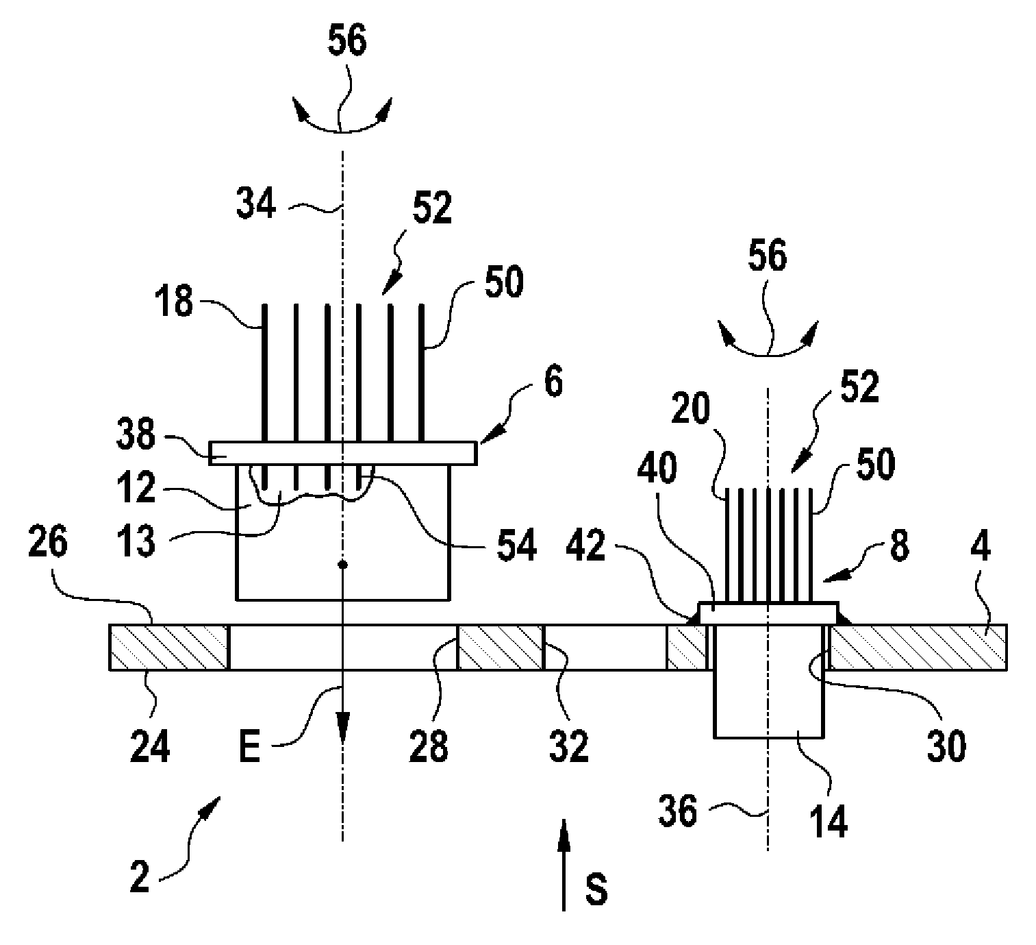
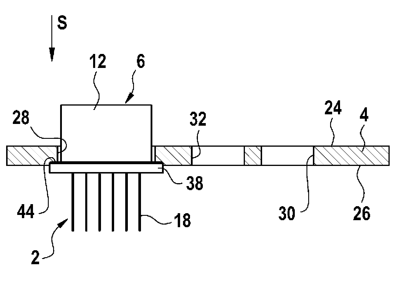
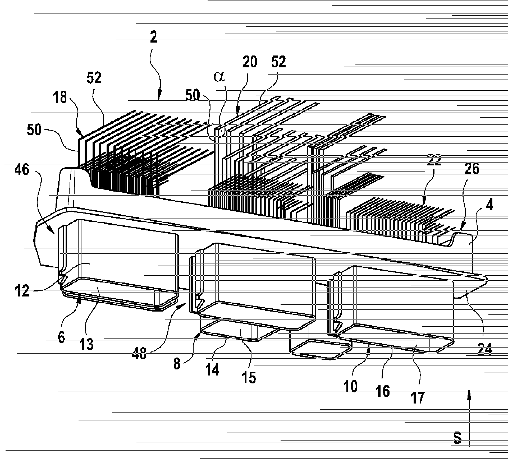
[0037] figure 1 A perspective view of a modular electrical plug-in connection device 2 is shown, which comprises a module base 4 and a first plug-in module 6 , a second plug-in module 8 and a third plug-in module 10 . In this case, the first plug-in module 6 , the second plug-in module 8 and the third plug-in module 10 are arranged either consecutively or side by side. A first plug housing 12 is formed on the first plug module 6 , a second plug housing 14 is formed on the second plug module 8 and a third plug housing 16 is formed on the third plug module 10 . . All plug housings 12 , 14 , 16 are designed to receive an electrical plug-in connector (not shown here) in each case along the plug-in direction S indicated by the arrow. Furthermore, a first contact element 18 is arranged in the first plug-in module 6 , a second contact element 20 is arranged in the second plug-in module 8 and a third contact element 22 is arranged in the third plug-in module 10 . In this case, the ...


PUM


Abstract

The invention relates to a modular electrical plug connector assembly for control units in a motor vehicle, comprising a module mounting (4) and at least one first plug-in module (6) and one second plug-in module (8), wherein the first plug-in module (6) and the second plug-in module (8) are arranged side-by-side and/or consecutively in the module mounting (4). The first plug-in module (6) is provided with a first plug housing (12), wherein the first plug housing (12) is configured to accommodate a first electrical plug connector. The second plug-in module (8) is provided with a second plug housing (14), wherein the second plug housing (14) is configured to accommodate a second electrical plug connector. The first plug housing (12) is provided with an electrically conductive first contact element (18), and the second plug housing (14) is provided with an electrically conductive second contact element (20). According to the invention, the first plug-in module (6) and the second plug-in module (8) are positioned relative to one another in the module substrate, and the first plug-in module (6) and the second plug-in module (8) are each permanently attached to the module mounting (4) by means of a fusion process.

Description

Background technique [0001] Many functions in today's motor vehicles are regulated or controlled by controllers. For example the timing of ignition, power fuel injection, but also electric window regulators or electric sliding sunroofs are also controlled or regulated via this controller. Currently, a concentration on a small number of controllers, with which multiple functions are controlled, can be noticed in the manufacture of motor vehicles. With the concentration on a few controllers, a higher number of electrical contacts occurs, with which on the one hand more actuators are controlled or regulated and on the other hand also more parameters are detected by the sensors. Furthermore, more and more sensors are to be installed, which in turn require further electrical contacts on the controller. If controls with significantly less than 100 contacts were manufactured in the 90's, controls with slightly less than 200 contacts are more common today. Efforts are currently bei...

Claims


Application Information

Patent Timeline
Patent Type & Authority Applications(China)
IPC IPC(8): H01R13/504H01R27/02
CPCH01R13/504H01R13/514H01R27/02H01R2201/26Y10T29/49208Y10T29/49213H01R33/90H01R43/26
Inventor R.克泽尔
Owner ROBERT BOSCH GMBH
Why Eureka
Try Eureka