

Hydraulic continuous drawing machine
A drawing machine and hydraulic technology, applied in the direction of wire drawing dies, etc., can solve the problems that the center of the product does not coincide with the center of the drawing, the continuous drawing process of the parts cannot be arranged, and the products are prone to defects, etc., so as to achieve low production cost and convenient The effect of popularization and simple structure
- Summary
- Abstract
- Description
- Claims
- Application Information
AI Technical Summary
Problems solved by technology
Method used
Image

Examples
Embodiment Construction
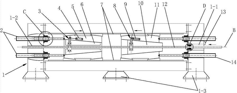
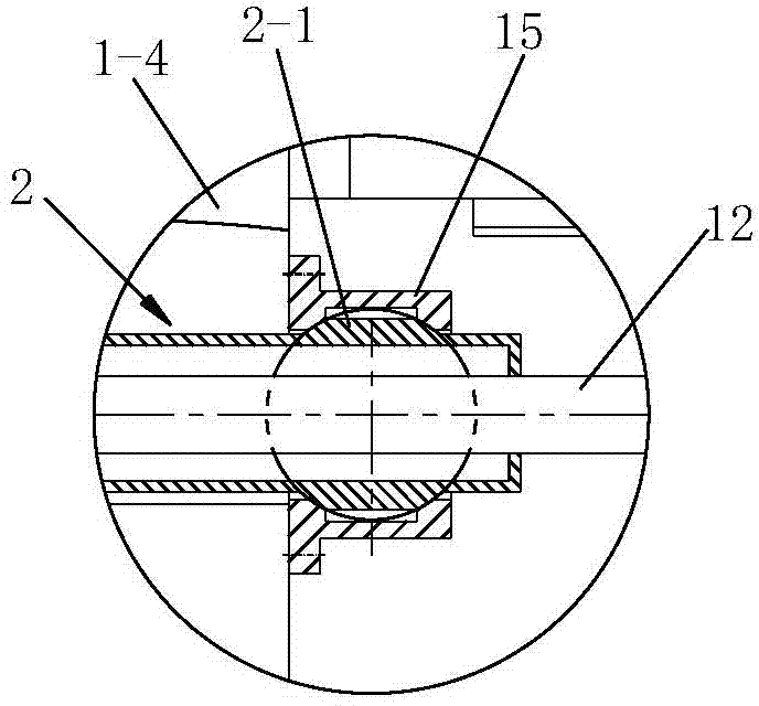
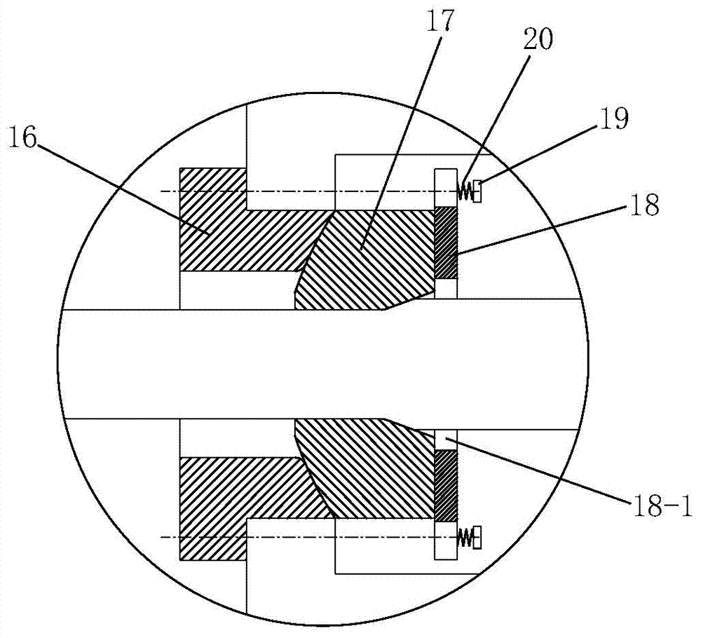
[0054] Such as figure 1 with Figure 4 A hydraulic continuous drawing machine shown includes a frame 1 and a left trolley 5 installed in the frame 1, a right trolley 11, two left drawing hydraulic cylinders 2 and two right drawing hydraulic cylinders 14, the frame 1 is a vertical structure, the frame 1 is provided with a feed channel 1-1 and a discharge channel 1-2 for the product 12 to pass through horizontally, and a product drawing die 17 is installed on the feed channel 1-1, The two left drawing hydraulic cylinders 2 are respectively located above and below the product 12, and the two right drawing hydraulic cylinders 14 are respectively located above and below the product 12. The cylinder body of the left drawing hydraulic cylinder 2 is installed On the left part of the frame 1, the piston rod of the left drawing hydraulic cylinder 2 is connected with the left trolley 5, and the cylinder body of the right drawing hydraulic cylinder 14 is installed on the right part of t...
PUM
 Abstract
Description
Claims
Application Information