Torque conversion differential assembly of coaxial motor

A technology of coaxial motors and differentials, which is applied in the direction of mechanical equipment, electric power devices, transmission parts, etc., can solve the problems of large space occupied by the chassis, poor balance, complex installation and suspension, etc., and achieve compact structure and balance Good, takes up little space

Active Publication Date: 2013-12-18
GEYUAN POWER
View PDF5 Cites 13 Cited by
  • Summary
  • Abstract
  • Description
  • Claims
  • Application Information

AI Technical Summary

Problems solved by technology

[0003] One is to drive the transmission box through the motor, and then the transmission box is connected to the drive shaft through the transmission shaft to carry out the walking operation. This driving form has the problem that the chassis takes up a lot of space and is not conducive to the layout of the vehicle's power battery; at the same time, it also relatively reduces The duty cycle of the power battery shortens the cruising range of the electric vehicle, which directly leads to a decline in the economy of the electric vehicle and a limited use environment;
[0004] The other is to directly connect the motor to the transmission box, and then the transmission box is connected to the driving bridge for walking operation. Since this driving form installs both the motor and the transmission box on the drive axle housing, there are many structural connection parts, and the installation suspension The installation is complicated and the process cost is high; moreover, because the vehicle will bump up and down when driving, the motor and transmission box will swing up and down around the drive axle, resulting in poor balance of the vehicle

Method used


Image

  • Torque conversion differential assembly of coaxial motor
  • Torque conversion differential assembly of coaxial motor
  • Torque conversion differential assembly of coaxial motor

Examples


Embodiment Construction

[0029] The present invention will be described in further detail below in conjunction with the accompanying drawings and embodiments, but these embodiments should not be construed as limiting the present invention.

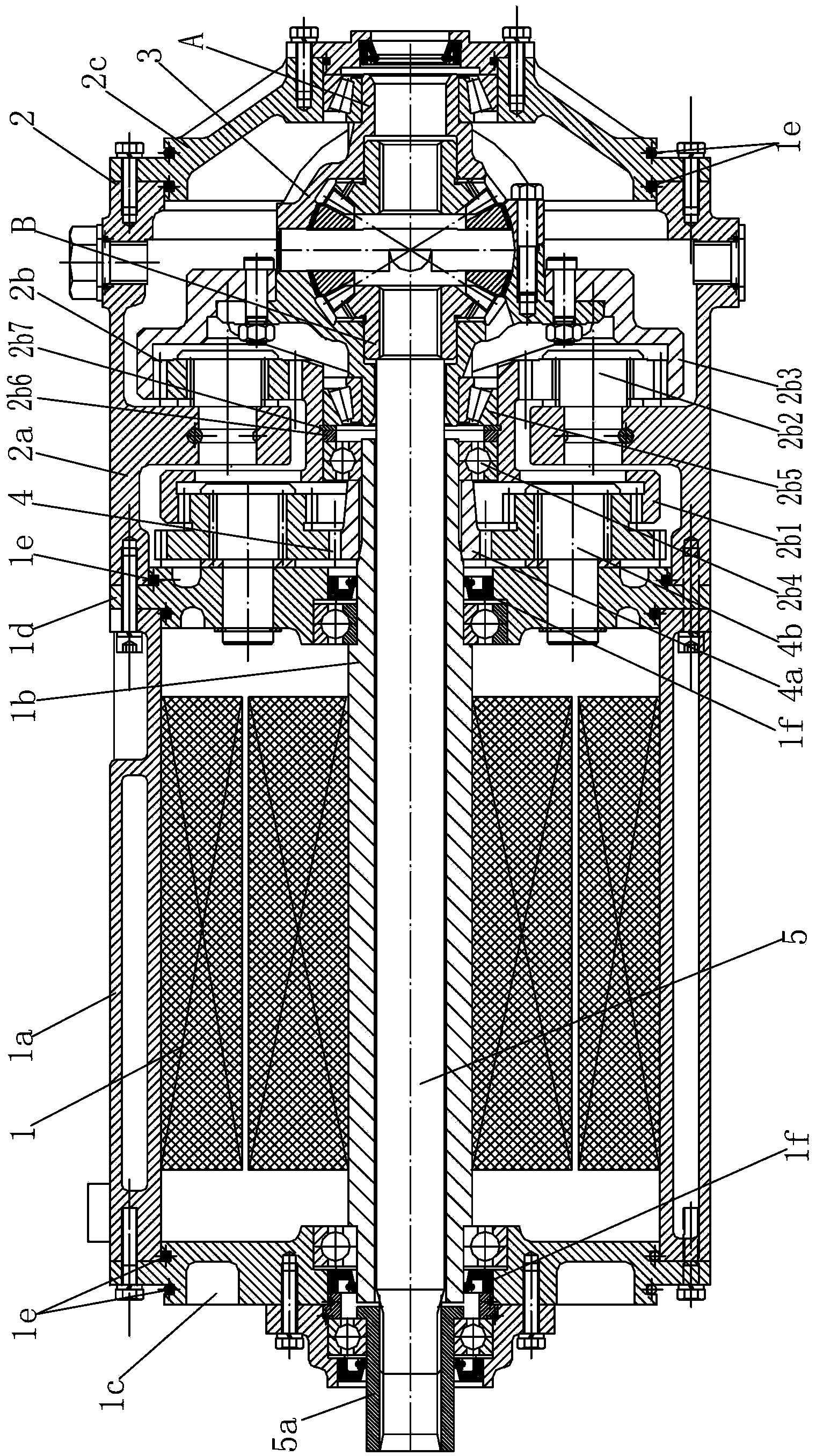
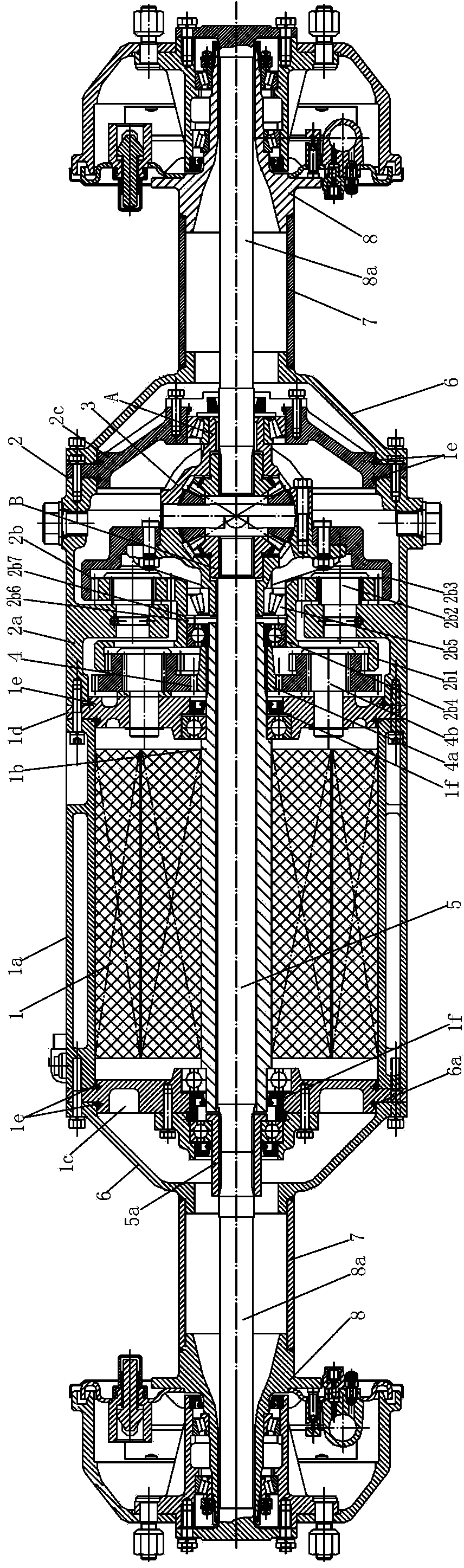
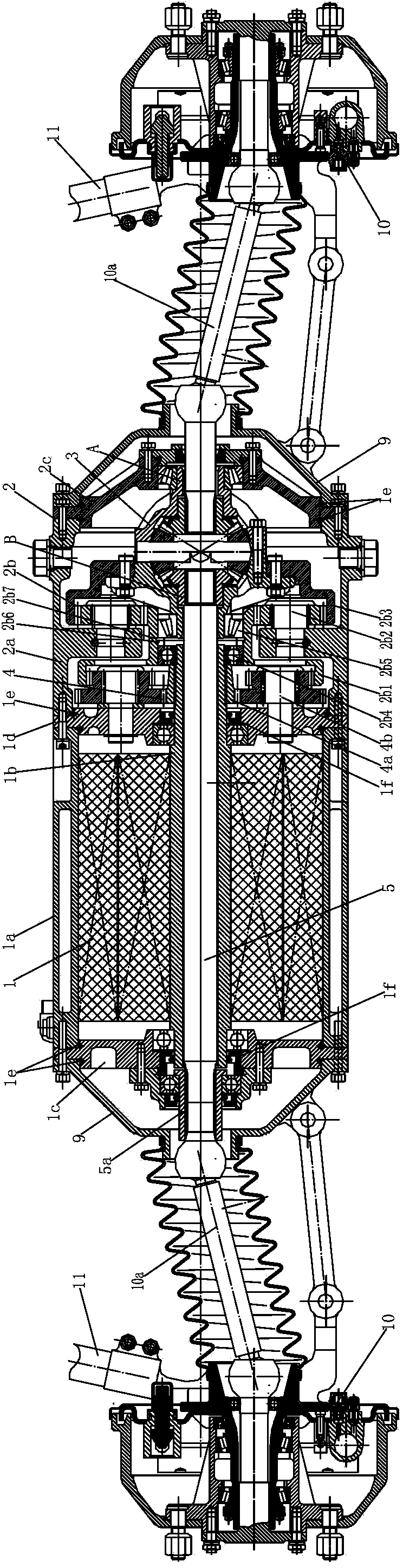
[0030]This embodiment provides a coaxial motor torque converter differential assembly, including a motor sub-assembly 1, a torque converter sub-assembly 2 and a differential sub-assembly 3, the motor sub-assembly 1 includes an electric The machine casing 1a, the motor rear end cover 1c and the motor front end cover 1d installed at both ends of the motor casing 1a respectively, and the rotor shaft 1b movably installed on the motor rear end cover 1c and the motor front end cover 1d, the The rotor shaft 1b is a hollow structure; the torque converter subassembly 2 includes a torque converter housing 2a, a transmission mechanism 2b installed in the torque converter housing 2a and a The torque converter end cover 2c at the front end of 2a, the rear end of the torque con...


PUM


Abstract

The invention discloses a torque conversion differential assembly of a coaxial motor. The torque conversion differential assembly comprises a motor sub-assembly, a torque converter sub-assembly and a differential sub-assembly. The motor sub-assembly comprises a motor shell, a motor rear end cover, a motor front end cover and a rotor shaft, the motor rear end cover and the motor front end cover are respectively mounted at two ends of the motor shell, and the rotor shaft is movably mounted on the motor rear end cover and the motor front end cover and is of a hollow structure; the torque converter sub-assembly comprises a torque converter shell, a speed change mechanism and a torque converter end cover, the torque converter end cover is mounted at the front end of the torque converter shell, the rear end of the torque converter shell is mounted on the motor front end cover, the front end of the rotor shaft is in transmission connection with an input end of the speed change mechanism, an output end of the speed change mechanism is fixed onto a shell of the differential sub-assembly, an output end B of the differential sub-assembly is mounted on the torque converter end cover, and an output end A and the output end B of the differential sub-assembly are coaxial with the rotor shaft. The torque conversion differential assembly has the advantages of small occupied space, good balance and applicability to vehicles.

Description

technical field [0001] The invention relates to a vehicle drive assembly, in particular to a coaxial motor torque converter differential assembly. Background technique [0002] With the rapid development of society, people have more and more functional requirements for electric vehicles, more and more space requirements, and higher performance requirements. At present, there are two main driving forms of general electric vehicles: [0003] One is to drive the transmission box through the motor, and then the transmission box is connected to the drive shaft through the transmission shaft to carry out the walking operation. This driving form has the problem that the chassis takes up a lot of space and is not conducive to the layout of the vehicle's power battery; at the same time, it also relatively reduces The duty cycle of the power battery shortens the cruising range of the electric vehicle, which directly leads to a decline in the economy of the electric vehicle and a limi...

Claims


Application Information

Patent Timeline
Patent Type & Authority Applications(China)
IPC IPC(8): B60K17/16B60K1/00F16H57/023
Inventor 岳国生王建东
Owner GEYUAN POWER
Why Eureka
Try Eureka