
Power output machine

A technology of power output and rotating rods, which is applied in the direction of engines, machines/engines, mechanical equipment, etc., to achieve the effect of small friction and reduced capacity loss

Inactive Publication Date: 2013-12-18
李三营
View PDF0 Cites 1 Cited by
  • Summary
  • Abstract
  • Description
  • Claims
  • Application Information

AI Technical Summary

Problems solved by technology

[0003] The purpose of the present invention is to provide a power output machine to solve the problem that the existing power output machine is limited by factors such as geography, environment and weather

Method used


Image

  • Power output machine
  • Power output machine
  • Power output machine

Examples


Embodiment

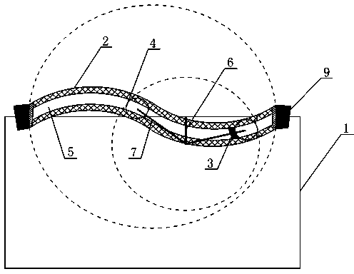
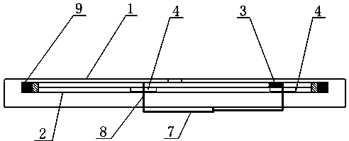
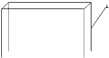
[0026] Such as Figure 1-6 As shown, a power take-off machine includes a support 1, a slideway 2 arranged on the support 1 and movably connected with it, and a slider 3 and a main bearing 4 arranged in the slideway 2; the support 1 is also provided with There is a control piece for controlling the motion track of the main bearing 4. The specific setting is that the slideway is connected with the support through the rotating shaft, and the control part is also connected with the support through the rotating shaft, and the control part and the slideway are not on the same plane, so figure 2 can be seen in.

[0027] The above-mentioned slideway 2 is a double-layer inner hollow structure, the slider 3 is located at the bottom layer, and the main bearing 4 is located at the top layer; the slideway 2 is also provided with a groove 5 that can communicate with the top layer and the bottom layer, and the control member wears Extend to the bottom layer through the groove 5; at the sa...


PUM


Abstract

The invention discloses a power output machine and solves the problem that existing power output machines are limited by factors like geography, environment and weather. The power output machine comprises a support, a slideway arranged on and movably connected with the support, a slider and two main bearings, the slider and the main bearings are arranged in the slideway, and a control member used for controlling motion tracks of the main bearings is further arranged on the support. Due to gravity, the slideway can rotate in a vertical plane relatively to the support; the slider is arranged in the slideway, and can slide in the slideway and increase gravity at a local position of the slideway, so that the slideway is enabled to rotate for a long time to output power; the main bearings are arranged in the slideway to limit the motion tracks of the slider and to guarantee a motion range of the slider in the slideway, so that long-time rotation of the slideway is realized better.

Description

technical field [0001] The invention specifically relates to a power take-off machine. Background technique [0002] At present, known power output machines have internal combustion engines and electric motors, etc., and they consume fuel oil and electric energy during work. With the deterioration of the energy resource situation, chemical energy is more and more in short supply, and it pollutes the environment very much. Although there are clean energy sources such as wind energy and solar energy as power sports machines in addition, they cannot be popularized on a large scale due to factors such as environment and geography. Therefore, it is imminent to invent and create a power output machine that is not restricted by factors such as geography, environment, and weather. Contents of the invention [0003] The object of the present invention is to provide a power take-off machine to solve the problem that the existing power take-off machine is limited by factors such as ...

Claims


Application Information

Patent Timeline
Patent Type & Authority Applications(China)
IPC IPC(8): F03G3/00
Inventor 李三营
Owner 李三营
Learn More