S-shaped profile blade of axial turbomachine compressor, corresponding compressor and turbomachine

A technology for turbines and compressors, applied in the fields of machine blades and compressors, to achieve the effect of reducing the vortex loss at the tip of the blade, reducing secondary losses, and increasing efficiency

Inactive Publication Date: 2013-12-18
SAFRAN AERO BOOSTERS SA
View PDF6 Cites 4 Cited by
  • Summary
  • Abstract
  • Description
  • Claims
  • Application Information

AI Technical Summary

Problems solved by technology

However, other types of losses exist, including eddy losses due to rotor tip leakage and secondary losses associated with fluid flow along the inner and outer walls of the fluid flow

Method used


Image

  • S-shaped profile blade of axial turbomachine compressor, corresponding compressor and turbomachine
  • S-shaped profile blade of axial turbomachine compressor, corresponding compressor and turbomachine
  • S-shaped profile blade of axial turbomachine compressor, corresponding compressor and turbomachine

Examples


Embodiment Construction

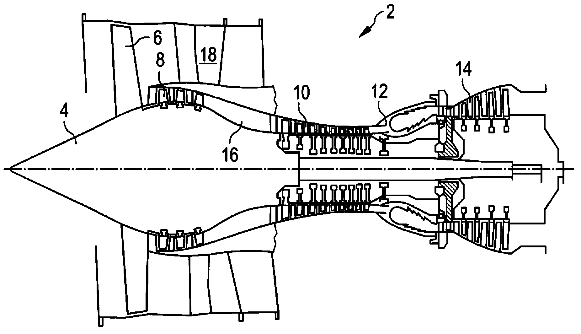
[0035] figure 1 An axial turbine 2 is shown schematically. In this case it is a two-way turbojet. Turbojet engine 2 actually comprises a first compressor stage called low-pressure compressor 8 , a second compressor stage called high-pressure compressor 10 , a combustion chamber 12 and one or more turbine stages 14 . In operation, the mechanical power of the turbine 14 is transmitted via the central shaft to the rotor 4 and drives the two compression stages 8 and 10 . Both compression stages include a plurality of rows of rotor blades associated with rows of stator blades. The rotation of the rotor thereby generates and gradually compresses the airflow to the inlet of the combustion chamber 12 . An inlet fan, commonly referred to as a turbofan 6, is coupled to the rotor 4 and generates an air flow that is divided into a primary flow 16 through the different stages of the above-mentioned turbine and through a ring extending along the length of the machine. The secondary flow...


PUM


Abstract

The invention relates to a subsonic rotor and/or stator blade profile of an axial turbomachine compressor, such as a turbojet. The blade has a leading edge with an S-shaped lateral profile in its mid-plane. Specifically, the profile includes, from its inner end to the outer end, a first convex portion including the foremost part of the blade, and a second concave portion including the rearmost area of the blade. This profile enables the fluid flow between 20% and 80% of the blade's length to be redistributed. This so-called 'sweep' profile increases the performance of the stage with such blades because it reduces blade tip vortex losses as well as secondary losses.

Description

technical field [0001] The present invention relates to the field of axial turbomachines, and more particularly to the compressors of such machines. The present invention relates to blades of such machines. Background technique [0002] WO 2009 / 103528 A2 discloses different blade geometries for axial turbines, including compressors of axial turbines. It discloses in particular a geometry in which the leading edge of the blade has a sinusoidal S-shaped profile. This description incorporates a blade formed over its entire section (or its chord) as well as over a section perpendicular thereto. In other words, the description combines so-called "sweep" and "lean" profiles, respectively. A so-called "swept" profile is formed along its length by "shifting" a segment along its axial chord direction. The "displacement" mentioned above is essentially an offset in a given direction of stacking of blade sections along their length, which can change direction. A so-called "sloped" ...

Claims


Application Information

Patent Timeline
Patent Type & Authority Applications(China)
IPC IPC(8): F04D29/38F01D5/14
CPCF01D5/141F04D29/324F05D2250/38F05D2250/70Y02T50/60F05D2250/75F04D29/384F04D29/544
Inventor V.伊利奥波洛
Owner SAFRAN AERO BOOSTERS SA
Why Eureka
Try Eureka