
Single particle fuel micro-combustion, gasification suspension, ignition, imaging and detection system

A detection system and micro-combustion technology, applied in particle and sedimentation analysis, analytical materials, measuring devices, etc., can solve the problems of the new micro-energy system such as small size, long-term power supply, long charging time, and difficult storage and portability of gas fuel.

Active Publication Date: 2013-12-18
HANGZHOU DIANZI UNIV
View PDF6 Cites 9 Cited by
  • Summary
  • Abstract
  • Description
  • Claims
  • Application Information

AI Technical Summary

Problems solved by technology

Most of the traditional micro-energy systems are powered by micro-lithium battery packs, but there are many shortcomings in the power supply of lithium-ion battery packs: low energy density, short power supply time, long charging time during repeated use, etc., so it is difficult to meet the small size of the new micro-energy system. , light weight, high energy density, uninterrupted long-term power supply, etc.
However, gas fuel is not easy to store and carry, which is a big problem for miniature aerospace equipment and portable equipment
So there is a question: Can micro-combustion fuel use liquid or solid micro-particle fuel?

Method used


Image

  • Single particle fuel micro-combustion, gasification suspension, ignition, imaging and detection system
  • Single particle fuel micro-combustion, gasification suspension, ignition, imaging and detection system
  • Single particle fuel micro-combustion, gasification suspension, ignition, imaging and detection system

Examples


Embodiment Construction

[0022] The present invention will be further described below in conjunction with accompanying drawing.

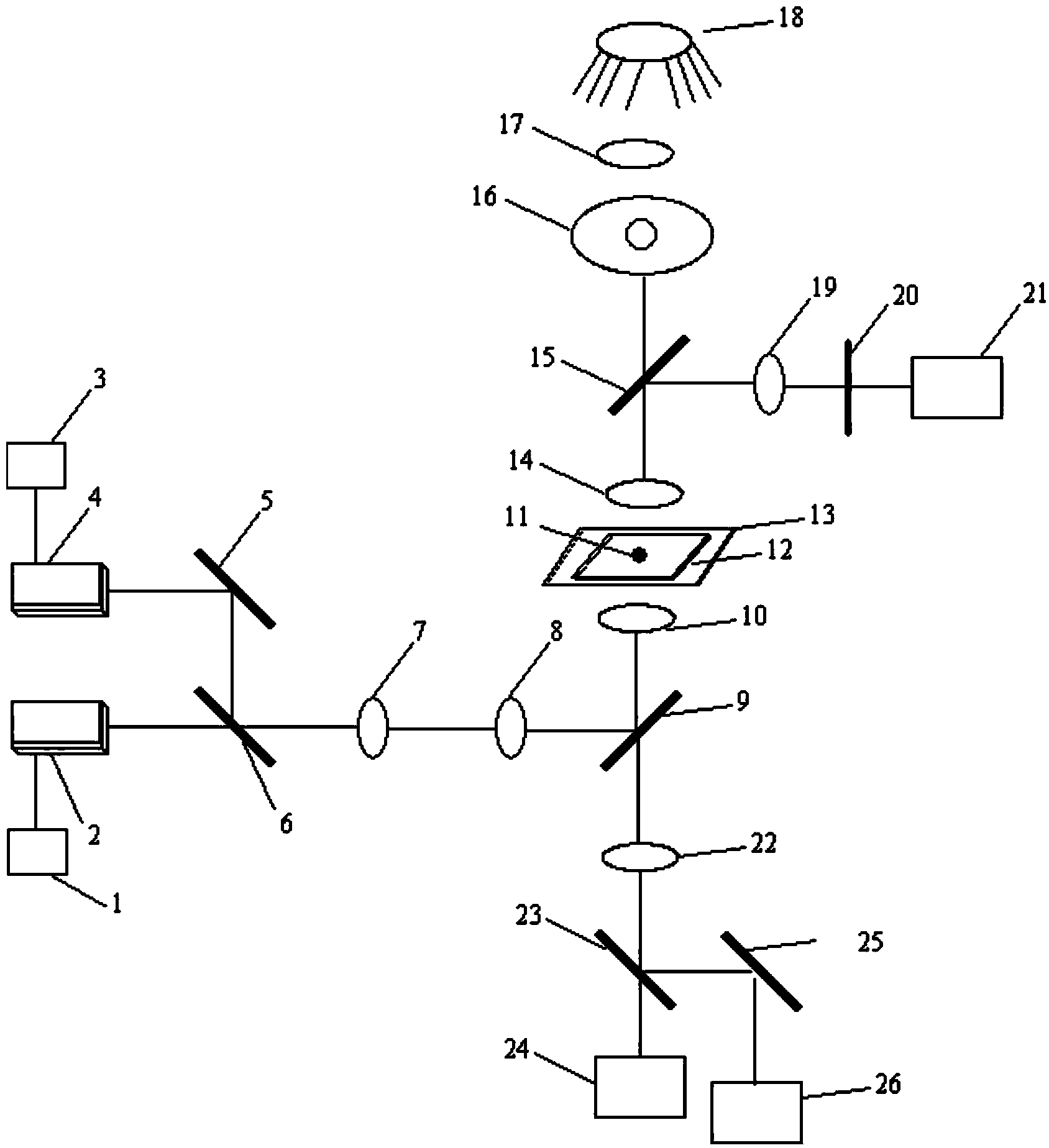
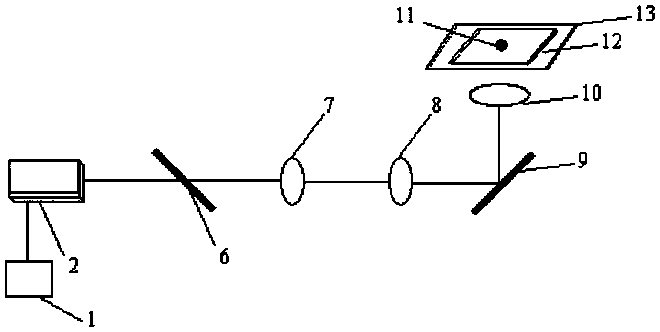
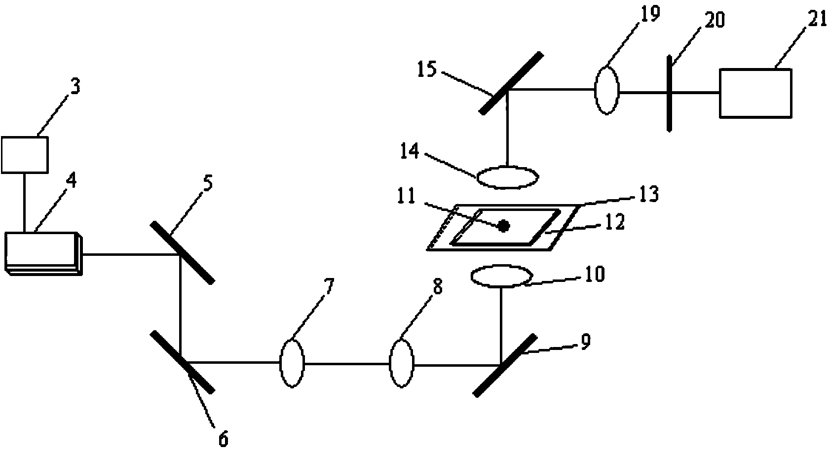
[0023] like figure 1 As shown: this embodiment mainly includes a first laser driver 1, a first laser 2, a second laser driver 3, a second laser 4, a first mirror 5, a first beam splitter 6, an inverted telescope 7, 8, a second laser Beam splitter 9, high magnification objective lens 10, micro-particle fuel 11, micro-combustion chip 12, three-dimensional electric displacement platform 13, condenser mirror 14, third beam splitter 15, iris diaphragm 16, light collector 17, light source 18, first lens 19. Optical filter 20 , four-quadrant detector 21 , second lens 22 , third beam splitter 23 , CCD camera 24 , second mirror 25 and infrared camera 26 .

[0024] The light emitted by the first laser 2 passes through the first beam splitter 6, the inverted telescope 7, 8, the second beam splitter 9 and the high-power objective lens 10 to form a focused spot to suspend the micro-par...


PUM


Abstract

The invention relates to a single particle fuel micro-combustion, gasification suspension, ignition, imaging and detection system. At present, common fuels used for microenergy systems based on micro-combustion are gas fuels which are difficult to store and carry. The system provided by the invention comprises a first laser driver, a first laser, a second laser driver, a second laser, a first reflection lens, a first spectroscope, an inverted telescope, a second spectroscope, a high-power objective lens, microparticle fuels, a micro-combustion chip, a three-dimensional electric displacement platform, a condensing lens, a third spectroscope, an iris diaphragm, a collecting lens, an optical source, a first lens, an optical filter, a four-quadrant detector, a second lens, a third spectroscope, a CCD (Charge Coupled Device) camera, a second reflection lens and an infrared camera. The all-optical particle suspension positioning, igniting and testing method is utilized to test the micro-combustion and the gasification of particles in a non-interference manner, so that the facticity of the micro-combustion and the gasification can be best reflected, the essence of the particles is restored and the mechanism of the particles is effectively revealed.

Description

technical field [0001] The invention belongs to the technical field of micro-combustion, and relates to a micro-combustion, gasification suspension, ignition, imaging and detection system of a single particulate fuel. Background technique [0002] With the development of micro-electro-mechanical systems (MEMS) technology, research on micro-energy systems has attracted extensive attention because it can meet the needs of long-term power supply for portable electronic devices and high-performance power sources and power sources for micro-miniature aerospace equipment. Such as micro / nano-satellites, micro-aircraft, "Army Warrior" individual combat system, robot ants, micro-energy systems for mobile electronic equipment, etc. Most of the traditional micro-energy systems are powered by micro-lithium battery packs, but there are many shortcomings in the power supply of lithium-ion battery packs: low energy density, short power supply time, long charging time during repeated use, e...

Claims


Application Information

Patent Timeline
IPC IPC(8): G01N15/00G01N15/02G01J5/00
Inventor 李盛姬黄雪峰
Owner HANGZHOU DIANZI UNIV
Learn More