
Method and device for counting the number of landings performed by an aircraft tyre

An aircraft and tire technology, applied in tire measurement, tire parts, instruments, etc., can solve problems such as weight increase and mass imbalance, and achieve the effect of weight reduction and low energy consumption

Active Publication Date: 2013-12-18
MICHELIN & CO CIE GEN DES ESTAB MICHELIN
View PDF7 Cites 3 Cited by
  • Summary
  • Abstract
  • Description
  • Claims
  • Application Information

AI Technical Summary

Problems solved by technology

However, during high-speed rotation of the tire, the weight increase creates an excessive mass imbalance

Method used


Image

  • Method and device for counting the number of landings performed by an aircraft tyre
  • Method and device for counting the number of landings performed by an aircraft tyre
  • Method and device for counting the number of landings performed by an aircraft tyre

Examples


Embodiment Construction

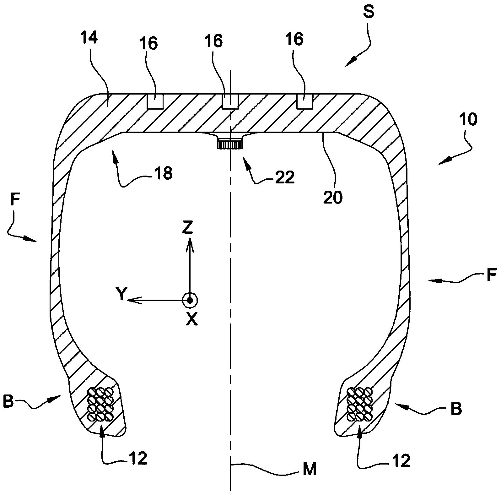
[0032] figure 1 A tire according to the invention is shown generally indicated at 10 . Tire 10 is designed to be mounted on aircraft wheels. figure 1 Mutually orthogonal axes X, Y, Z are shown, corresponding to the usual radial (Z), axial (Y) and circumferential (X) orientation of the tyre.

[0033] Conventionally, the tire 10 includes a crown S extending through two sidewalls F and two inner beads B. As shown in FIG. Two steel wire cores 12 are embedded in the inner bead B. The two wire cores 12 are arranged symmetrically with respect to the radial mid-plane M of the tyre. Each wire core 12 rotates about a reference axis. This axis of reference is substantially parallel to the direction Y and substantially coincides with the axis of rotation of the tyre. The crown S comprises a tread 14 equipped with sculptured features 16 . The tire 10 also includes an inner layer of leak-proof rubber 18 that runs across the crown S between the two annular wire cores 12 of the tire 10 ...


PUM


Abstract

The invention relates to a method for counting the number of landings performed by an aircraft tyre, comprising the following steps in which: a physical quantity relating to the air inside the tyre is measured in a non-continuous manner; at least one indicator relating to the physical quantity is determined; the indicator is compared with a predetermined threshold associated with the tyre; and, if the indicator is greater than the predetermined threshold, the number of landings is increased.

Description

technical field [0001] The invention relates to the field of landing gear tires for aircraft. Background technique [0002] The tire wear of an aircraft depends on the number of landings and takeoffs it undergoes. The number of landings is equal to the number of takeoffs. [0003] On the one hand, the manufacturer needs to know this number of landings or take-offs to monitor tire wear and understand how tire performance changes with tire wear. On the other hand, the various actors intervening in the aircraft (maintenance services, inspection services, etc.) need to be able to participate in the replacement or reconditioning of worn tires. [0004] By document FR2939897, and a method and device for counting the number of landings of aircraft tires. The device is attached to the inner surface of the tire. The device includes sensors and means for powering the device, such as a battery. The sensor comprises a coil sensitive to the temporal variation of the magnetic flux ge...

Claims


Application Information

Patent Timeline
IPC IPC(8): G07C5/08B64C25/00G01L17/00
CPCB64D2045/008G07C5/085B60C23/0477B64F5/60
Inventor L·法戈-勒维拉特
Owner MICHELIN & CO CIE GEN DES ESTAB MICHELIN
Learn More