Thoracic cavity puncture equipment

A kind of equipment and thoracic technology, applied in puncture needles, medical science, surgery, etc., can solve the problems of poor measurement and evaluation of manual puncture accuracy, and achieve the effect of ingenious design, convenient operation, and simple configuration

Inactive Publication Date: 2013-12-25
关美玉
View PDF5 Cites 1 Cited by
  • Summary
  • Abstract
  • Description
  • Claims
  • Application Information

AI Technical Summary

Problems solved by technology

However, when the puncture point is in the thoracic cavity, because there are ribs blocking it, oblique puncture should be performed in the rib gap. For example, in the field of thoracentesis, the puncture point is required to be between the 7th and 9th intercostals under the scapula or the 6th or 7th intercostal space on the axillary midline. , can pump out g

Method used


Image

  • Thoracic cavity puncture equipment
  • Thoracic cavity puncture equipment

Examples


Embodiment approach 1

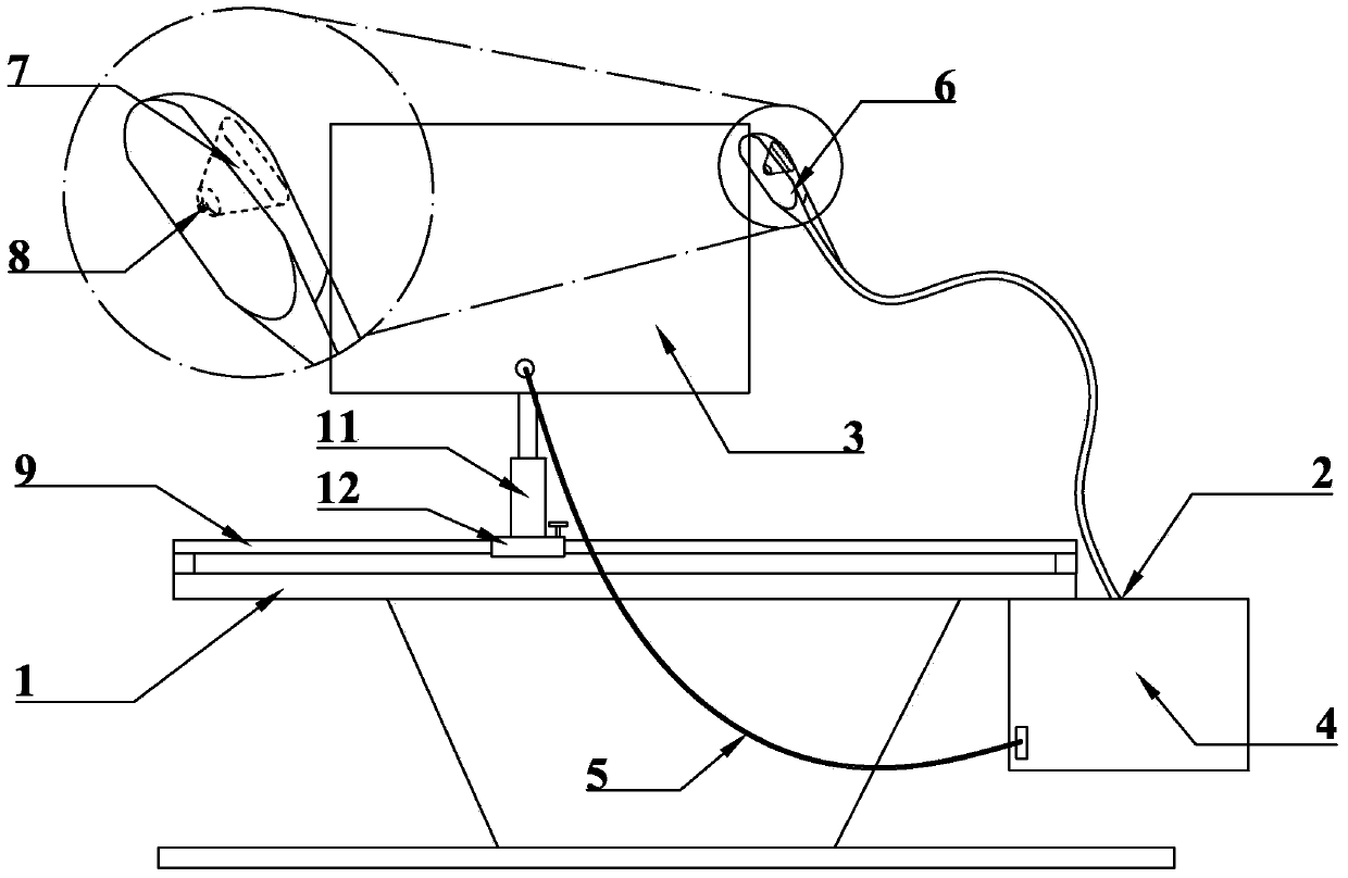
[0018] Implementation mode one: if figure 1 As shown, the thoracentesis equipment includes an operating table 1 for the patient to lie on and a B-ultrasound machine 2 connected to the operating table 1, and a real-time monitor 3 is slipped on the operating table 1, and the B-ultrasound machine 2 includes a host 4, an image data transmission line 5 and a probe 6, wherein one end of the image data transmission line 5 is connected to the host 4, and the other end is connected to the input end of the real-time monitor 3; the probe 6 is provided with a puncture groove 7 , the puncture groove 7 is provided with a puncture needle position hole 8 at the bottom, and its groove shape is gradually fan-shaped upwards.

[0019] The edge of the console 1 is provided with a track, and the real-time monitor 3 is slid on the track. The track is elliptical, and it is a guide rod 9 connected end to end. The lower end of the real-time monitor 3 is provided with a guide rail connection mechanism...

Embodiment approach 2

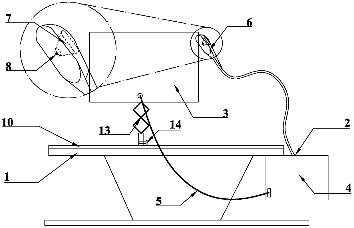
[0020] Implementation mode two: if figure 2 As shown, the thoracentesis equipment includes an operating table 1 for the patient to lie on and a B-ultrasound machine 2 connected to the operating table 1, and a real-time monitor 3 is slipped on the operating table 1, and the B-ultrasound machine 2 includes a host 4, an image data transmission line 5 and a probe 6, wherein one end of the image data transmission line 5 is connected to the host 4, and the other end is connected to the input end of the real-time monitor 3; the probe 6 is provided with a puncture groove 7 , the puncture groove 7 is provided with a puncture needle position hole 8 at the bottom, and its groove shape is gradually fan-shaped upwards.

[0021] The edge of the console 1 is provided with a track, and the real-time monitor 3 is slid on the track. Said track is elliptical, and it is a guide groove 10 connected end to end. The lower end of the real-time monitor 3 is provided with a guide groove connection m...


PUM

PropertyMeasurementUnit
Widthaaaaaaaaaa
Diameteraaaaaaaaaa

Abstract

The invention relates to thoracic cavity puncture equipment. Commonly, firstly, B-ultrasonic waves are adopted to carry out positioning; then a doctor carries out manual puncture according to experience. Due to blockage of ribs in the thoracentesis, inclined puncture needs to be carried out in gaps of the ribs. The thoracic cavity puncture equipment comprises an operation desk and a B-ultrasonic wave machine, wherein the operation desk is used for a patient to lie down; the B-ultrasonic wave machine is connected to the operation desk; a real-time monitor is arranged on the operation desk in a sliding manner; the B-ultrasonic wave machine comprises a host, an image data transmission line and a probe; one end of the image data transmission line is connected to the host, and the other end of the image data transmission line is connected with the input end of the real-time monitor; the probe is provided with a puncture groove; the bottom of the puncture groove is provided with a puncture needle position hole; the groove shape of the puncture groove gradually expands upwards in a sector shape. According to the invention, by transforming the probe structure and integrating B-ultrasonic wave positioning and real-time monitoring on the whole puncture process on one continuous operation desk, the thoracic cavity puncture equipment is particularly suitable for thoracic cavity positioning angle puncture.

Description

technical field [0001] The invention relates to a thoracentesis device. Background technique [0002] At present, thoracentesis is performed first by B-ultrasound positioning, and then manual puncture is performed by doctors based on experience. If the puncture point is in the abdomen, a vertical puncture can be performed. However, when the puncture point is in the thoracic cavity, because there are ribs blocking it, oblique puncture should be performed in the rib gap. For example, in the field of thoracentesis, the puncture point is required to be between the 7th and 9th intercostals under the scapula or the 6th or 7th intercostal space on the axillary midline. , can pump out gas to treat pneumothorax, and at the same time, can also pump out inflammatory exudate in the pleural cavity, or inject drugs to treat pleurisy and relieve respiratory distress symptoms. The liquid can be used for various purposes such as laboratory tests and bacterial culture. Or misjudgment, the a...

Claims


Application Information

Patent Timeline
IPC IPC(8): A61B17/34A61B19/00
Inventor 关美玉孙继泽刘晓军孙博文
Owner 关美玉
Why Eureka
Try Eureka