Remote state monitoring system of fire hydrant

A remote monitoring system and fire hydrant technology, applied in fire rescue and other fields, can solve problems such as poor supervision, frequent occurrence of fire safety hazards, delay in rescue time, etc., and achieve the effects of helping maintenance and management, promoting healthy development, and saving rescue time

Active Publication Date: 2013-12-25
福建风向标工程技术有限公司
View PDF2 Cites 29 Cited by
  • Summary
  • Abstract
  • Description
  • Claims
  • Application Information

AI Technical Summary

Problems solved by technology

As an important part of public fire-fighting facilities to ensure the safety of people's lives and properties, fire hydrants are lagging behind in supporting construction, inadequate maintenance, and outdated supervision methods, which seriously affect the timely extinguishment of fires and cannot well protect the lives and properties of the people. Safety
[0003] In the existing technology, the existing fire hydrants have the following deficiencies: 1) The water pressure in the hydrant cannot be displayed. Once a fire occurs, it is necessary to turn on the fire alarm to know whether there is water and whether the pressure is enough, which delays the precious rescue time; 2) Management When personnel overhaul fire hydrants, they must go to the site to check whether the appearance is intact and whether there is water leakage. The water outlet valve must be opened to test the water pressure, which wastes a lot of manpower, energy and material resources;

Method used


Image

  • Remote state monitoring system of fire hydrant
  • Remote state monitoring system of fire hydrant
  • Remote state monitoring system of fire hydrant

Examples


Embodiment Construction

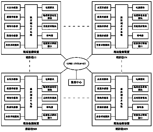
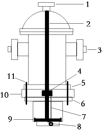
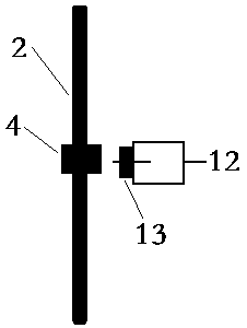
[0016] The fire hydrant state remote monitoring system of the present invention, such as figure 1 As shown, it includes an on-site detection device located on a fire hydrant and a remote monitoring center, and the on-site detection device includes a water pressure sensor, a flow sensor, an inclination sensor, an anti-pry sensor, a geographic information positioning module, and a micro-control chip circuit and wireless transmitter module. like figure 2 As shown, the water pressure sensor 8 is installed on the front end of the fire hydrant water-stop pad 9 to detect the water pressure, and is connected to the micro-control chip circuit through the wire 7 (the wire has enough length to cope with the water-stop pad being opened at will. resulting displacement). like image 3 As shown, the tamper-resistant sensor 12 is composed of a reed switch 13 and a permanent magnet 4 arranged on the fire hydrant valve stem 2 for cooperating with the reed switch 13. After the action of the ...


PUM


Abstract

The invention relates to a remote state monitoring system of a fire hydrant. The remote state monitoring system comprises a site detection device arranged on the fire hydrant, and a monitoring center positioned at a remote end, wherein the site detection device comprises a water pressure sensor, a flow sensor, a tilt angle sensor, a prying-resistant sensor, a geographic information positioning module, an identity recognition module, a buzzer, a microcontrol chip circuit and a wireless transmission module, wherein the water pressure sensor is positioned at the front end of a water stop pad and is connected with the microcontrol chip circuit, the prying-resistant sensor comprises a reed switch and a permanent magnet arranged on a fire hydrant valve rod for being matched with the reed switch to work, the reed switch outputs a signal after acting and the signal is output to the microcontrol chip circuit, and the microcontrol chip circuit transmits the acquired data to the monitoring center through a star topology structure of the wireless transmission module of the fire hydrant in a region and in a self-networking or relaying manner and then through a wireless network. The remote state monitoring system is capable of remotely monitoring the state of the fire hydrant, preventing the fire hydrant from being illegally used, displaced and damaged, and providing relevant information of the fire hydrant to maintenance or fire emergency of the personnel patrol.

Description

technical field [0001] The invention relates to the technical field of state monitoring of fire-fighting facilities, in particular to a remote monitoring system for the state of fire hydrants. Background technique [0002] The rapid development of economy and the rapid expansion of cities make the task of fire prevention increasingly difficult. As an important part of public fire-fighting facilities to ensure the safety of people's lives and properties, fire hydrants are lagging behind in supporting construction, inadequate maintenance, and outdated supervision methods, which seriously affect the timely extinguishment of fires and cannot well protect the lives and properties of the people. Safety. [0003] In the existing technology, the existing fire hydrants have the following deficiencies: 1) The water pressure in the hydrant cannot be displayed. Once a fire occurs, it is necessary to turn on the fire alarm to know whether there is water and whether the pressure is enoug...

Claims


Application Information

Patent Timeline
IPC IPC(8): A62C37/50
Inventor 刘荣山
Owner 福建风向标工程技术有限公司
Why Eureka
Try Eureka