Rolling grouser method and rolling grouser structure

A technology of crawling and rolling friction, which is applied in the field of crawler, can solve problems such as the collapse of the internal structure of rubber molecules, consumption of friction power consumption, unfavorable energy conservation and environmental protection, etc., and achieve the goal of reducing a large number of thermal effects, reducing friction torque, and saving internal friction Effect

Inactive Publication Date: 2013-12-25
CHONGQING NENGMA TECH
View PDF5 Cites 2 Cited by
  • Summary
  • Abstract
  • Description
  • Claims
  • Application Information

AI Technical Summary

Problems solved by technology

[0002] The current crawler device mainly relies on the interaction between the spurs on the crawler track and the wheel body including supporting rollers, guide pulleys, tensioning wheels, and driving wheels to guide the direction of the track. While acting as a guide belt, the mutual sliding friction movement consumes a lot of friction power consumption, especially on rubber crawlers, the friction guide belt function of the track is usually completed by the driving teeth, and the longitudinal end faces of some driving teeth It needs to cooperate with the driving teeth of the driving wheel to play the role of driving the belt, and the transverse end face of some driving teeth usually cooperates with various wheel bodies of the track to act as a transverse guide belt, and the rubber track in contact with the wheel body will generate heat due to friction. The phenomenon is more serious. The friction between the shoe and the wheel body causes a large amount of molecular thermal effect on the internal molecules of the rubber parts. Under long-term interaction and high-speed sliding friction, the thermal effect of the internal molecules of the rubber can easily lead to the collapse of the internal structure of the rubber molecules, resulting in The track is damaged, which constitutes a great potential safety hazard. The traditional track and the wheel body cooperate with sliding friction, which causes greater wear on the track and consumes a lot of motion, which is not conducive to energy conservation and environmental protection.

Method used


Image

  • Rolling grouser method and rolling grouser structure
  • Rolling grouser method and rolling grouser structure
  • Rolling grouser method and rolling grouser structure

Examples


Embodiment Construction

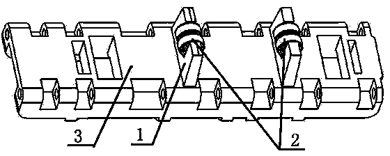
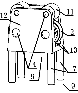
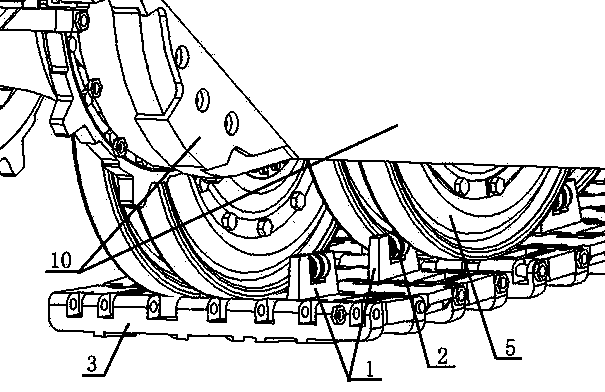
[0032] refer to figure 1 , image 3 , Figure 4As shown, the first embodiment of the present invention is the application of rolling crawlers on traditional crawlers and tank trolleys, including crawlers made of crawlers, crawlers, latches, etc., and driven wheels, tension wheels, supporting weights, etc. The wheel body (5) that wheel forms, and car body (10). The shoe (3) is provided with a shoe base (1), which is concave in the longitudinal direction, and in the middle of the concave shape of the shoe base (1) is placed a longitudinally fixed shoe base ( 1) The longitudinal axis (4) on the front and rear ends of the concave shape, the longitudinal axis (4) is fixed on the shoe base (1), and two rollers (2) are arranged side by side longitudinally on the longitudinal axis (4) To increase the longitudinal length of the rolling track to an appropriate length, the outer arc surface of the roller (2) protrudes from the lateral end face (13) of the track base, and conflicts wit...


PUM


Abstract

The invention relates to a rolling grouser method and a rolling grouser structure. The rolling grouser method is adopted, rolling friction matching between a grouser and wheel bodies replaces traditional sliding friction matching, rollers capable of rotating transversely are fixedly disposed at the positions, where the grouser and the wheel bodies transversely and mutually butt against, on a crawler device, the rollers are matched with the side faces of the crawler wheel bodies in a rolling manner, and through rolling and butting against matching, transverse force on various wheel bodies on the crawler device is transmitted to a crawler to guide a moving direction of the crawler. The rolling grouser structure designed with the rolling grouser method is adopted to match with the wheel bodies of the crawler device, so that friction force between the grouser and the various wheel bodies can be reduced effectively, and particularly internal molecular structure heat effect caused by sliding friction of a rubber crawler is reduced, and internal molecular structural collapse caused by heat effect temperature rising of the rubber crawler is avoided effectively.

Description

technical field [0001] This invention relates to track rolling devices and, more particularly, to track spurs. Background technique [0002] The current crawler device mainly relies on the interaction between the spurs on the crawler track and the wheel body including supporting rollers, guide pulleys, tensioning wheels, and driving wheels to guide the direction of the track. While acting as a guide belt, the mutual sliding friction movement consumes a lot of friction power consumption, especially on rubber crawlers, the friction guide belt function of the track is usually completed by the driving teeth, and the longitudinal end faces of some driving teeth It needs to cooperate with the driving teeth of the driving wheel to play the role of driving the belt, and the transverse end face of some driving teeth usually cooperates with various wheel bodies of the track to act as a transverse guide belt, and the rubber track in contact with the wheel body will generate heat due to...

Claims


Application Information

Patent Timeline
Patent Type & Authority Applications(China)
IPC IPC(8): B62D55/18
Inventor 孙继华
Owner CHONGQING NENGMA TECH
Why Eureka
Try Eureka