Material pushing device of waste transfer station

A garbage transfer station and material pushing device technology, which is applied in the direction of garbage cans, garbage collection, household appliances, etc., can solve the problems of increasing labor time and labor intensity of workers, high equipment maintenance costs, and affecting timely removal of garbage, etc., to achieve Good pushing effect, reduced labor time and labor intensity, simple structure

Active Publication Date: 2015-06-17
CHONGQING ENDURANCE & SHINMAYWA IND
View PDF11 Cites 3 Cited by
  • Summary
  • Abstract
  • Description
  • Claims
  • Application Information

AI Technical Summary

Problems solved by technology

There are mainly two types of existing pusher devices, one is a large pusher device, which is very large in size and requires a steel plate conveyor belt, a large special feeding device, etc., requiring a large building area and increasing the construction cost. High manufacturing cost and high equipment maintenance cost
The other is that the small-scale pushing device, also known as the attached pusher, has a small processing capacity and cannot be dumped by large garbage collection vehicles. It can only meet the needs of small garbage collection vehicles, and the garbage is easily thrown outside
The garbage storage capacity is small, which is likely to cause congestion of collection vehicles during peak hours, affecting the timely removal of garbage, and increasing the labor time and labor intensity of workers

Method used


Image

  • Material pushing device of waste transfer station
  • Material pushing device of waste transfer station
  • Material pushing device of waste transfer station

Examples


Embodiment Construction

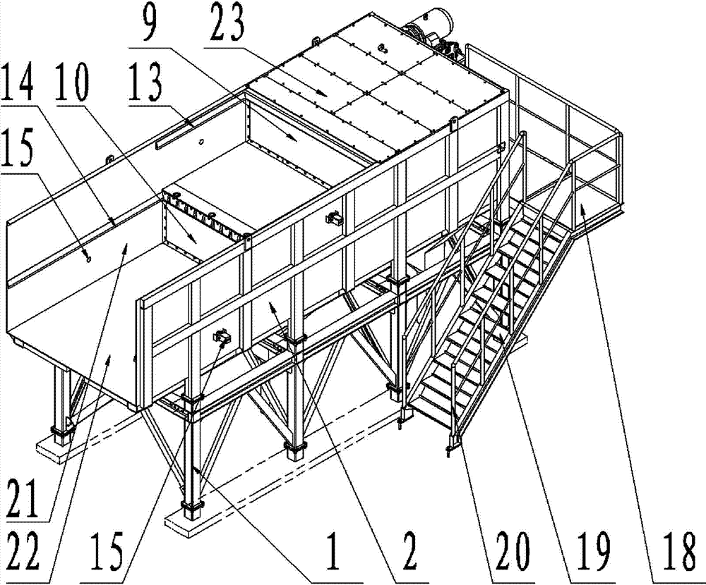
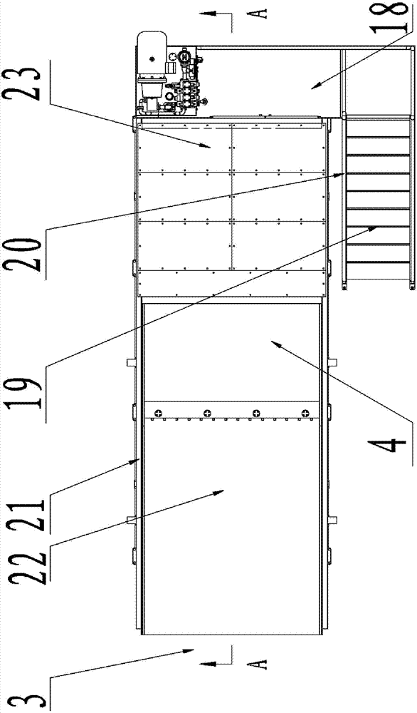
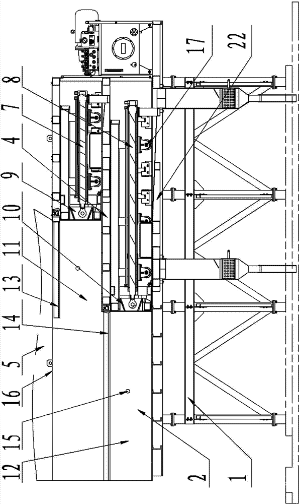
[0031] see Figure 1 ~ Figure 3, is an embodiment of the pushing device of the garbage transfer station, including a frame 1, further, the frame 1 is composed of welded steel, and the structure of the frame can be changed according to the matching garbage compression equipment , can work well with various types of garbage pushing equipment. A working frame 2 is fixed on the top of the frame 1, and the frame and the working frame are fixedly connected by bolts, and the upper end of the working frame 2 is connected with a discharge chute 5. Further, the working frame 2 includes two side plates 21, a bottom plate 22 and a top plate 23, the two side plates 21 are fixed on the left and right sides of the bottom plate 22, the bottom plate is connected with the frame, and the top plate 23 is fixed on the two side plates 21 above. Further, the two side plates 21 and the bottom plate 22 are respectively welded as a whole by section steel and steel plate. Further, an inspection platf...


PUM


Abstract

The invention discloses a material pushing device of a waste transfer station. The material pushing device of the waste transfer station comprises a rack, wherein a working framework is fixed to the top of the rack, a discharge chute is connected with the upper end of the working framework, material pushing oil cylinders are installed in the working framework, material pushing heads are installed on the material pushing oil cylinders, discharge chambers are arranged in front of the material pushing heads, the discharge chambers are communicated with the discharge chute, the material pushing heads comprise the upper material pushing head and the lower material pushing head, the upper material pushing head is arranged on the upper rear portion of the lower material pushing head, the discharge chambers comprise the upper discharge chamber and the lower discharge chamber, an upper pushing head guide rail is arranged on the portion, corresponding to the upper material pushing head, of the side wall of the upper discharge chamber, a lower pushing head guide rail is arranged on the portion, corresponding to the lower material pushing head, of the side wall of the lower discharge chamber, the material pushing oil cylinders comprise the upper material pushing oil cylinder and the lower material pushing oil cylinder, a piston rod of the upper material pushing oil cylinder is connected with the upper material pushing head, and a piston rod of the lower material pushing oil cylinder is connected with the lower material pushing head. The material pushing device of the waste transfer station is good in waste treatment and storage capacity, the requirement of material dumping of various waste collection vehicles can be met, the phenomenon that the waste collection vehicles block up is avoided, the labor time and labor intensity of workers are reduced, normal operation of the waste transfer station is ensured, the required covered area is small, and manufacturing cost and maintenance cost are low.

Description

technical field [0001] The invention relates to the field of garbage transfer stations, in particular to a material pushing device for a garbage transfer station. Background technique [0002] The role of the garbage transfer station is to transport the scattered garbage collected from residents, units, commercial and public places, etc. here for concentration, and compress and reduce the scattered garbage through a special device, and then put it into a special container , sent by the transport vehicle to the final waste disposal site for final disposal, such as landfill, incineration, composting, etc. [0003] In the process of garbage processing, the unloading chute of the garbage transfer station first temporarily stores the garbage collected by the collection vehicle in it, and then sends the garbage into the compressor through the pushing device for compression processing. Therefore, the insufficient storage capacity of the unloading chute will cause the congestion of...

Claims


Application Information

Patent Timeline
Patent Type & Authority Patents(China)
IPC IPC(8): B65F1/12
Inventor 彭佳张向杰段勇周刚洪贤
Owner CHONGQING ENDURANCE & SHINMAYWA IND
Why Eureka
Try Eureka