Loading and unloading system
A loading and unloading system and system application technology, which is applied in the direction of transportation and packaging, conveyors, mechanical conveyors, etc., can solve problems such as poor safety, low intelligence level, and high labor intensity, and achieve automation, strong scalability, and application wide range of effects
- Summary
- Abstract
- Description
- Claims
- Application Information
AI Technical Summary
Problems solved by technology
Method used
Image

Examples
Embodiment 1
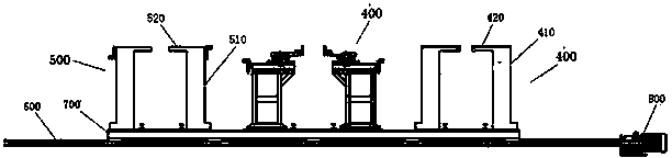
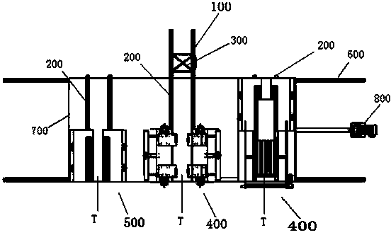
[0024] see figure 1 and figure 2 , a loading and unloading system for a processing production line in the heavy equipment manufacturing industry, the system includes a main rail 100 extending to the processing equipment of the production line, a plurality of loading and unloading rails 200 arranged in the same direction as the main rail 100, running on The transport vehicle 300 on the main track 100 , at least one loading platform 400 and at least one unloading platform 500 . Wherein: the plurality of loading and unloading rails 200 are located at the end of the main rail 100, and each of the loading and unloading rails 200 can reciprocate along a direction perpendicular to the main rail 100, for realizing each of the loading and unloading The rails 200 can be respectively docked with the main rail 100; the at least one loading platform 400 and the at least one unloading platform 500 are respectively fixed on the corresponding loading and unloading rails 200, and can be sync...
Embodiment 2
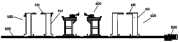
[0029] This embodiment is an improvement on the basis of the first embodiment, and only the distinguishing features are described here. The other features of this embodiment are the same as those of the first embodiment, and also belong to the protection content of this embodiment. Specifically, see Figure 4 The difference between this embodiment and Embodiment 1 is that in this embodiment, the sliding base 700 is removed, and a plurality of the loading and unloading rails 200 are respectively directly installed on the secondary rail 600, and each loading and unloading rail 200 can be placed on the secondary rail 600 respectively. Move back and forth on the sub-track 600 to improve the flexibility of moving up and down the track in the system. Wherein, each loading and unloading track 200 can be respectively connected with a driving mechanism 800 for separately driving each loading and unloading track 200 to reciprocate.
[0030] It should be noted that in the above-mentione...
Embodiment 3
[0032] This embodiment is a specific application example of this system, that is, it is applied in a welding production line to improve the automation level of the welding production line.
[0033] like Figure 5As shown, the main rail 100 of the system extends to a welding production line composed of a plurality of welding machines 20, that is, a plurality of branch rails 10 are arranged on both sides of the main rail 100, and each branch rail 10 is provided for realizing The welding machine 20 of automatic welding can be, for example, this welding machine 20 comprises two positioners respectively positioned at the two sides of the support track 10, a mechanical welding arm installed above the positioner and a frock installed between the two positioners components. During specific operations, the transport vehicle 300 loads the parts to be welded (processed parts) from the corresponding loading table 400, and runs to the corresponding welding machine 20 through the loading a...
PUM
 Abstract
Description
Claims
Application Information
 - R&D
- Intellectual Property
- Life Sciences
- Materials
- Tech Scout
- Unparalleled Data Quality
- Higher Quality Content
- 60% Fewer Hallucinations
Browse by: Latest US Patents, China's latest patents, Technical Efficacy Thesaurus, Application Domain, Technology Topic, Popular Technical Reports.
© 2025 PatSnap. All rights reserved.Legal|Privacy policy|Modern Slavery Act Transparency Statement|Sitemap|About US| Contact US: help@patsnap.com