
Automatic stacking system

A technology of palletizing system and motion mechanism, which is applied in the direction of object stacking, object destacking, transportation and packaging, etc. Aging and other issues, to achieve the effect of easy installation of equipment, avoiding unbalanced situations, and prolonging life

Active Publication Date: 2013-12-25
SHENZHEN INST OF ADVANCED TECH CHINESE ACAD OF SCI
View PDF4 Cites 24 Cited by
  • Summary
  • Abstract
  • Description
  • Claims
  • Application Information

AI Technical Summary

Problems solved by technology

However, in the above scheme, the stroke of the manipulator needs to cover the middle part of the production line and the loading trays on both sides. The average stroke for placing a single product is long, resulting in low efficiency, and also leads to the overall high-precision processing size of the palletizing frame. bigger, more expensive
In addition, because the lifting device of the pallet rack itself is also placed on the machine body, when there are many products stacked on one side, it is easy to cause the weight imbalance on both sides of the equipment, and the rack is easy to age

Method used


Image

  • Automatic stacking system
  • Automatic stacking system
  • Automatic stacking system

Examples


Embodiment Construction

[0011] The present invention will be described in further detail below in conjunction with specific embodiments and accompanying drawings. Embodiments of the present invention are described in detail below, examples of which are shown in the drawings, wherein the same or similar reference numerals designate the same or similar elements or elements having the same or similar functions throughout. The embodiments described below with reference to the accompanying drawings are exemplary, and are only used to explain the technical solution of the present invention, and should not be construed as limiting the present invention.

[0012] In the description of the present invention, the orientation or positional relationship indicated by the terms "inner", "outer", "longitudinal", "transverse", "upper", "lower", "top", "bottom" etc. are based on the drawings The orientations or positional relationships shown are only for the convenience of describing the invention and do not require ...


PUM


Abstract

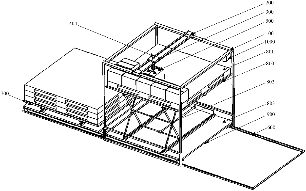
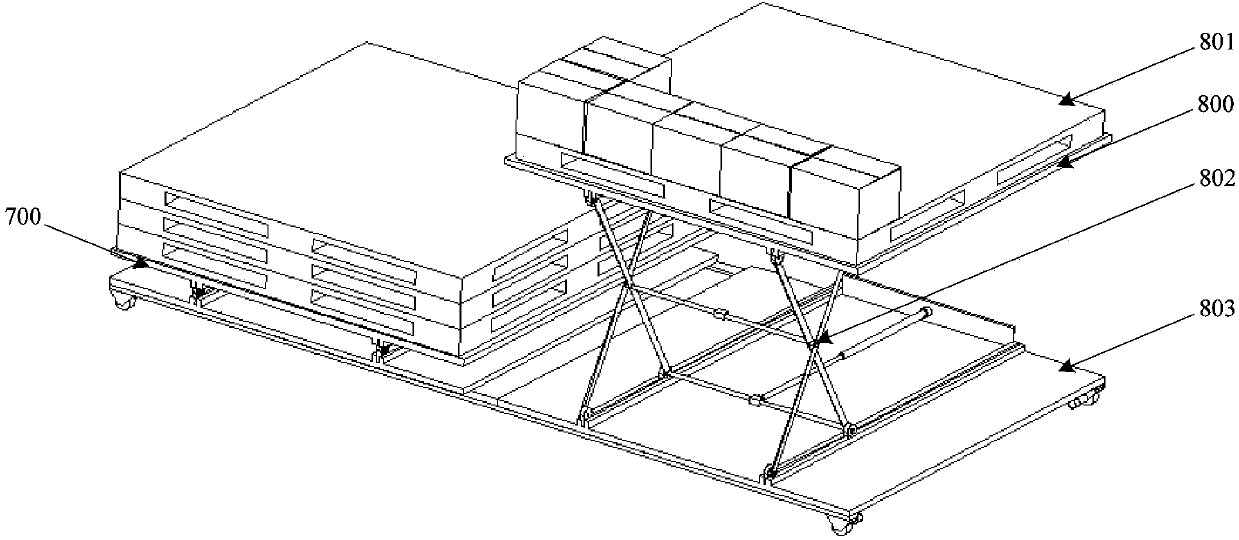
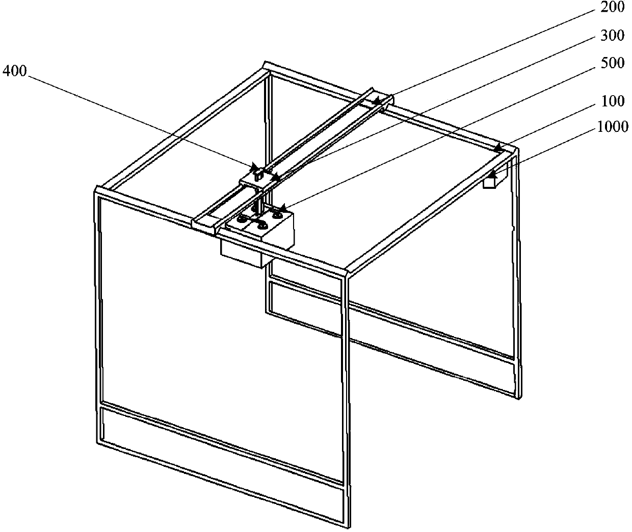
The invention relates to an automatic stacking system which comprises a frame, a first horizontal moving mechanism, a second horizontal moving mechanism, a vertical moving mechanism, a mechanical arm, a main guide rail, at least two pallet platform components, a first transmission mechanism, a first communication module, a distance sensor and a control box. Each pallet platform component comprises a pallet platform, a lifting mechanism for controlling the pallet platform to move up and down and a translation mechanism, the pallet platform is fixedly connected with the translation mechanism through the lifting mechanism, the translation mechanism is bridged on the main guide rail, and the lifting mechanism and the translation mechanism are connected with the first transmission mechanism. The first communication module is electrically connected with the control box. By the automatic stacking system, motion displacement for stacking goods of the mechanical arm can be reduced, goods stacking efficiency can be increased, burden of a mechanical arm motor is relieved, service life of the mechanical arm motor and related parts is prolonged, and cost is lowered.

Description

【Technical field】 [0001] The invention relates to an automatic palletizing system. 【Background technique】 [0002] Palletizer is a kind of equipment applied to the end of product production line to palletize products. Its principle is to put several products of the same batch into a pallet, and then transfer the products by forklift. [0003] Common palletizers in the prior art mainly include mechanical arm palletizers and high-position palletizers. The mechanical arm palletizer generally adopts multi-joint mechanical arm technology and is driven by hydraulic pressure. Its structure and control are relatively complicated and the cost is high; the high-position palletizer occupies a large area and the equipment is relatively heavy, and its movement and installation are extremely inconvenient. In addition, the above two palletizers are generally only equipped with a single pallet, that is, after a palletizing is completed, it is necessary to wait for the forklift to remove th...

Claims


Application Information

Patent Timeline
Patent Type & Authority Applications(China)
IPC IPC(8): B65G57/03B65G61/00
Inventor 王建军朱青松岳冰心谢耀钦
Owner SHENZHEN INST OF ADVANCED TECH CHINESE ACAD OF SCI
Learn More