Hanging tool for wafer electroplating

A technology for wafers and plated holes, which is applied to circuits, electrolytic components, electrolytic processes, etc., can solve problems such as large cost increases, complicated operating procedures, and time-wasting, and achieve simple and convenient locking methods, reduce operating procedures, and reduce cost effect

A technology for wafers and plated holes, which is applied to circuits, electrolytic components, electrolytic processes, etc., can solve problems such as large cost increases, complicated operating procedures, and time-wasting, and achieve simple and convenient locking methods, reduce operating procedures, and reduce cost effect

CN103469271AActive Publication Date: 2013-12-25江苏矽智半导体科技有限公司

Image

  • Hanging tool for wafer electroplating
  • Hanging tool for wafer electroplating
  • Hanging tool for wafer electroplating

Examples


Embodiment 1

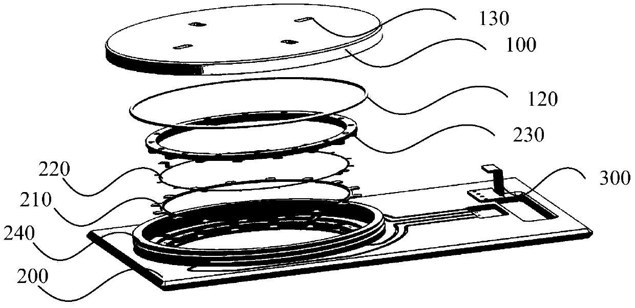
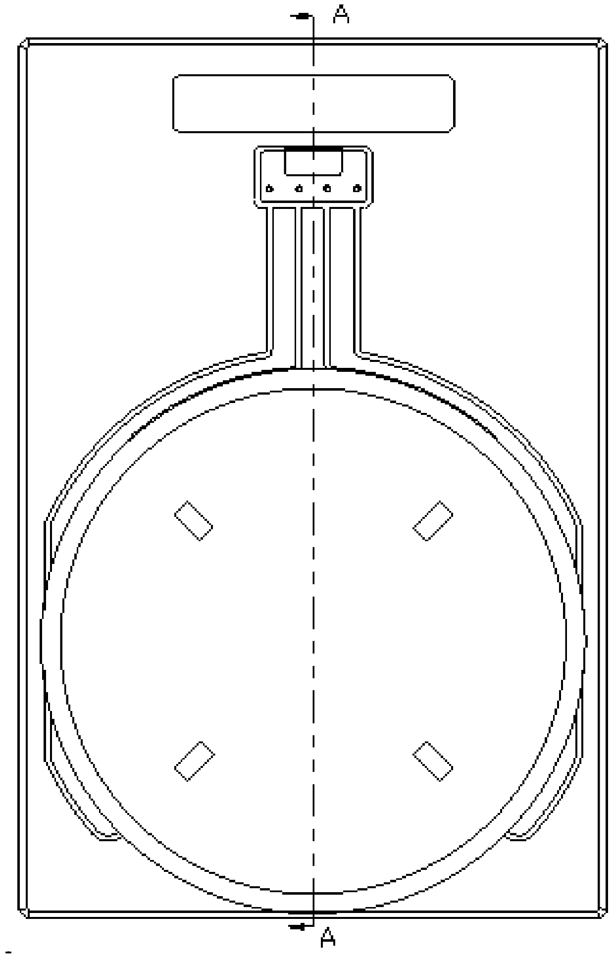
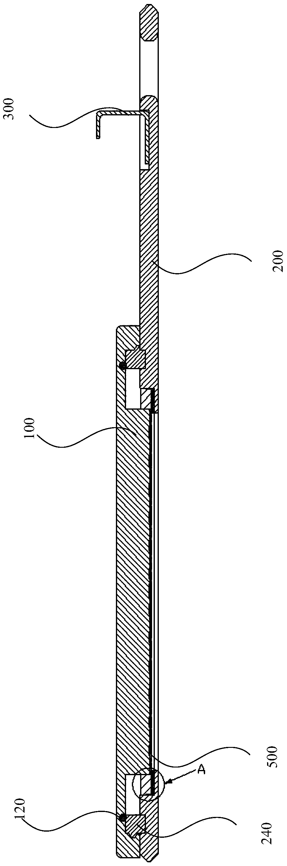
[0048] Embodiment 1 provides a hanger for wafer electroplating, such as Figure 1-9As shown, it includes an upper cover 100 and a lower plate 200. The upper cover 100 is also provided with an upper cover sealing ring 120; the lower plate 200 is provided with a wafer tank, a wafer tank wall 240, a sealing assembly, a metal conductive ring 220, Conductive copper plate 300, conductive copper plate groove 310, wire groove 400, electroplating hole 260, hanging part 280, etc.

[0049] The inner wall of the upper cover 100 is provided with an internal thread, and the outer wall of the wafer tank is provided with an external thread engaged with the internal thread. The upper cover 100 and the wall 240 of the wafer tank can be locked by rotating 90-3600 degrees. The wafer tank wall 240 and the lower plate 200 are fixedly connected or detachably connected. In this embodiment, the wafer tank wall 240 and the lower plate 200 are detachable structures;

[0050] A plating hole 260 is opene...


PUM


Abstract

The invention discloses a hanging tool for wafer electroplating. The hanging tool comprises an upper cover, a lower plate and a metal conductive ring, wherein an inner thread is arranged on the inner wall of the upper cover, a wafer groove is formed in the lower plate, an electroplating hole is formed in the middle of the wafer groove, and an outer thread engaged with the inner thread is arranged on the outer wall of the wafer groove; a platform is arranged between the inner wall of the wafer groove and the electroplating hole; the metal conductive ring is arranged on the platform. The upper cover of the hanging tool for the wafer electroplating is locked in a rotary mode, and the need of manually disassembling screws is eliminated, so that the hanging tool is convenient to operate, uniform in force, good in electrical conductivity and sealing performance and uniform in water coating, thereby greatly saving the manpower and reducing the wafer scrapping risk.

Description

technical field [0001] The invention relates to a wafer electroplating device of semiconductor electroplating equipment, in particular to a wafer electroplating hanger. Background technique [0002] The wafer plating hanger in the semiconductor electroplating equipment currently on the market is fixed by screws, which has the following disadvantages: 1. The operation procedure is relatively complicated, that is, when the wafer hanger is installed once, all the firm screws must be unscrewed before it can be opened. The upper cover of the hanger, after the wafer is installed, the above work must be repeated again to seal the wafer in the hanger; 2. If the existing hanger is not installed properly, it will directly affect the uniformity of the wafer surface coating , electrical conductivity, and the requirements for the screw material used on the surface of the hanger are very high, and the cost increases greatly; every time a wafer is installed in the hanger during on-site ope...

Claims


Application Information

Patent Timeline
25 Dec 2013
Publication
CN103469271A
IPC
C25D7/12; C25D17/08
Inventors
王江锋; 陈建平