Assembling type floor formwork system with preset anchor nuts

A prefabricated and nut technology, which is applied in the treatment of formwork, formwork/formwork/work frame, and on-site preparation of building components, etc., can solve the problems of wasting labor, damage, and cannot be reused, and achieves easy turnover. Use and solve the effect of labor-intensive

Active Publication Date: 2013-12-25
NANTONG CONSTR PROJECT GENERAL CONTRACTING
View PDF5 Cites 3 Cited by
  • Summary
  • Abstract
  • Description
  • Claims
  • Application Information

AI Technical Summary

Problems solved by technology

[0002] In the current floor formwork support system, the formwork panel and the steel truss are generally connected in a non-detachable fixed connection, that is, after the concrete floor is poured, the formwork panel is directly concealed in the suspended ceiling, or for houses without a suspended ceiling. It is said that after the construction, it is necessary to manually destroy the solder joints between the steel truss and the formwork panel, and remove the formwork panel supporting the concrete floor. It is seriously damaged and cannot be reused, which is a waste of labor and cost
[0003] With the requirement of reusable formwork panels, the assembled floor formwork system with detachable formwork panels has also appeared. The formwork panels and steel trusses are connected through movable connectors. The formwork panels and steel trusses are movable connections. The panel is detachable and reusable, which is convenient for turnover and reduces the construction cost. However, the current movable connectors are generally directly connected to the formwork panel and the steel truss, and there are no other auxiliary connectors.

Method used


Image

  • Assembling type floor formwork system with preset anchor nuts
  • Assembling type floor formwork system with preset anchor nuts
  • Assembling type floor formwork system with preset anchor nuts

Examples


Embodiment Construction

[0029] The present invention will be further described below in conjunction with the accompanying drawings.

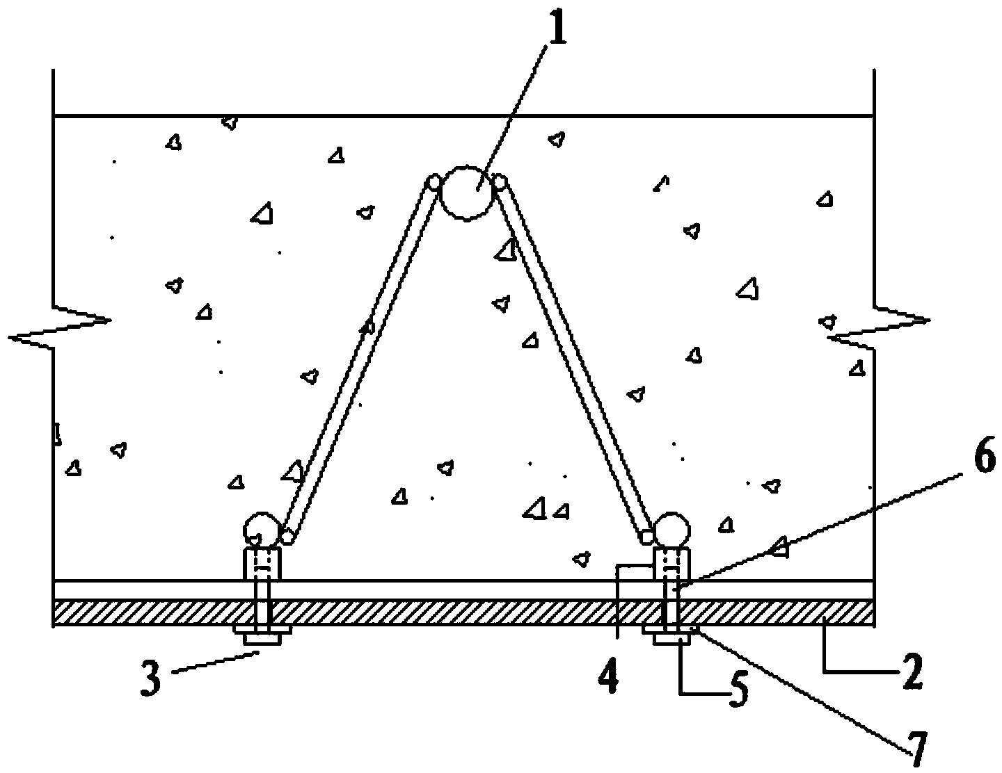
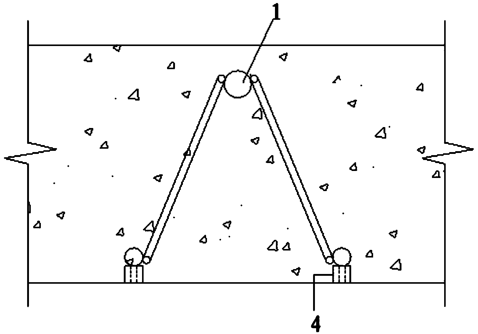
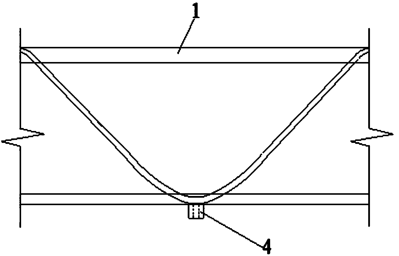
[0030] Such as Figure 1-6 As shown, a floor formwork support system with prefabricated anchor nuts, including: a steel truss 1, a formwork panel 2 and a fixed connection unit 3 for connecting the steel truss 1 and formwork panel 2, is characterized in that: The fixed connection unit 3 includes a lifting point nut 4 and a load-bearing screw 5, the lifting point nut 4 is fixedly connected to the main reinforcement of the lower chord of the steel bar truss 1, and the load-bearing screw 5 includes a screw 6 and a gasket 7. The screw rod 6 passes through the gasket 7, the template panel 2 and the concrete protective layer in turn and then screws into the lifting point nut 4, and the template panel 2 is provided with a plurality of through holes 8 for passing through the screw rod 6 .

[0031] The lifting point nut 4 is used to control the thickness of the concrete protec...


PUM


Abstract

The invention provides an assembling type floor formwork system with preset anchor nuts. The assembling type floor formwork system comprises a reinforcing steel bar truss (1), a template panel (2) and fixing and connecting units (3), wherein the fixing and connecting units (3) are used for connecting the reinforcing steel bar truss (1) and the template panel (2); the assembling type floor formwork system is characterized in that each fixing and connecting unit (3) comprises a lifting point nut (4) and a force bearing screw rod (5), the lifting point nut (4) is fixedly connected to a lower-chord main reinforcement of the reinforcing steel bar truss (1), the force bearing screw rod (5) comprises a screw rod (6) and a gasket (7), and the screw rod (6) is screwed in the lifting point nut (4) after sequentially penetrating through the gasket (7), the template panel (2) and a concrete protecting cover. According to the assembling type floor formwork system with the preset anchor nuts, provided by the invention, the reinforcing steel bar truss and the template panel are movably connected by utilizing the lifting point nut, the turnover use of building materials such as the template panel is convenient, and the problems of large amount of labor employment, serious waste and the like of a concrete floor formwork are solved.

Description

technical field [0001] The invention relates to an assembled floor formwork system with preset anchor nuts, which is suitable for on-site pouring or factory prefabrication of reinforced concrete frame structures, shear wall structures or steel structures in civil engineering, and belongs to the technical field of building construction. Background technique [0002] In the current floor formwork support system, the formwork panel and the steel truss are generally connected in a non-detachable fixed connection, that is, after the concrete floor is poured, the formwork panel is directly concealed in the suspended ceiling, or for houses without a suspended ceiling. It is said that after the construction, it is necessary to manually destroy the solder joints between the steel truss and the formwork panel, and remove the formwork panel supporting the concrete floor. Seriously damaged and cannot be reused, it is a waste of labor and cost. [0003] With the requirement of reusable ...

Claims


Application Information

Patent Timeline
IPC IPC(8): E04G11/36E04G11/48E04G17/00E04G17/18E04G19/00
Inventor 陈耀钢王永泉张军
Owner NANTONG CONSTR PROJECT GENERAL CONTRACTING
Why Eureka
Try Eureka