Plasma flow visualization device based on dielectric barrier discharge principle

A technology of dielectric barrier discharge and plasma, which is applied in measuring devices, fluid dynamics tests, and testing of machine/structural components. Convenient, simple and compact structure

Active Publication Date: 2013-12-25
INST OF ENGINEERING THERMOPHYSICS - CHINESE ACAD OF SCI
View PDF2 Cites 11 Cited by
  • Summary
  • Abstract
  • Description
  • Claims
  • Application Information

AI Technical Summary

Problems solved by technology

[0009] In view of this, the main purpose of the present invention is to provide a plasma flow display device based on the principle of dielectric barrier discharge, to solve the problems of existing flow display measurement equipment that interferes with the flow field and poor tracer particle tracking, and achieve qualitative and The purpose of quantitatively analyzing the complex flow mechanism inside the turbomachinery

Method used


Image

  • Plasma flow visualization device based on dielectric barrier discharge principle
  • Plasma flow visualization device based on dielectric barrier discharge principle
  • Plasma flow visualization device based on dielectric barrier discharge principle

Examples


Embodiment Construction

[0032] In order to make the object, technical solution and advantages of the present invention clearer, the present invention will be described in further detail below in conjunction with specific embodiments and with reference to the accompanying drawings.

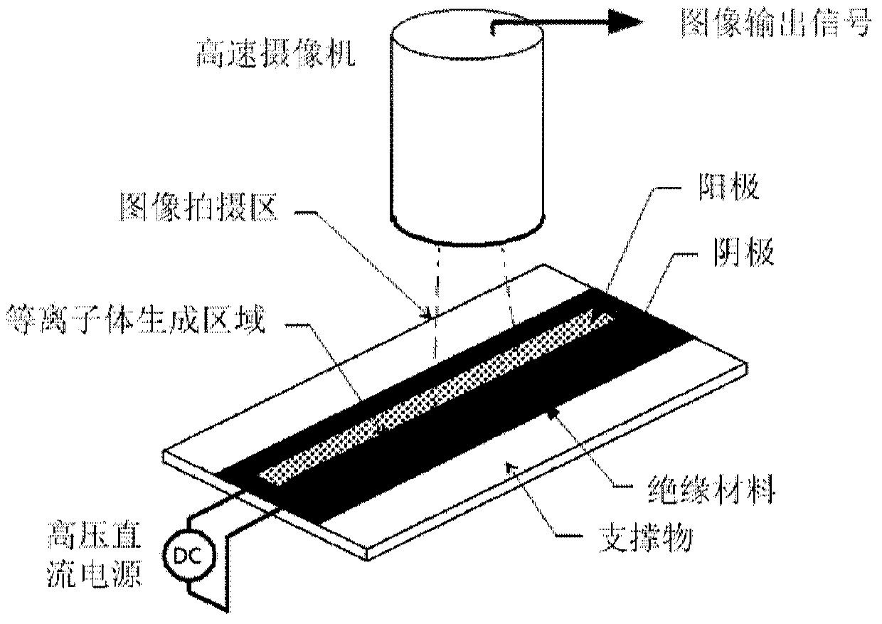
[0033] In order to break through the various limitations of the current non-contact measurement, the present invention proposes a plasma flow field display device based on the principle of dielectric barrier discharge. The plasma flow field display device can directly use the plasma ionized by the flow field molecules as a "display Tracking Particles”, breaking through the bottleneck of the limited display of tracer particles on the real flow field.

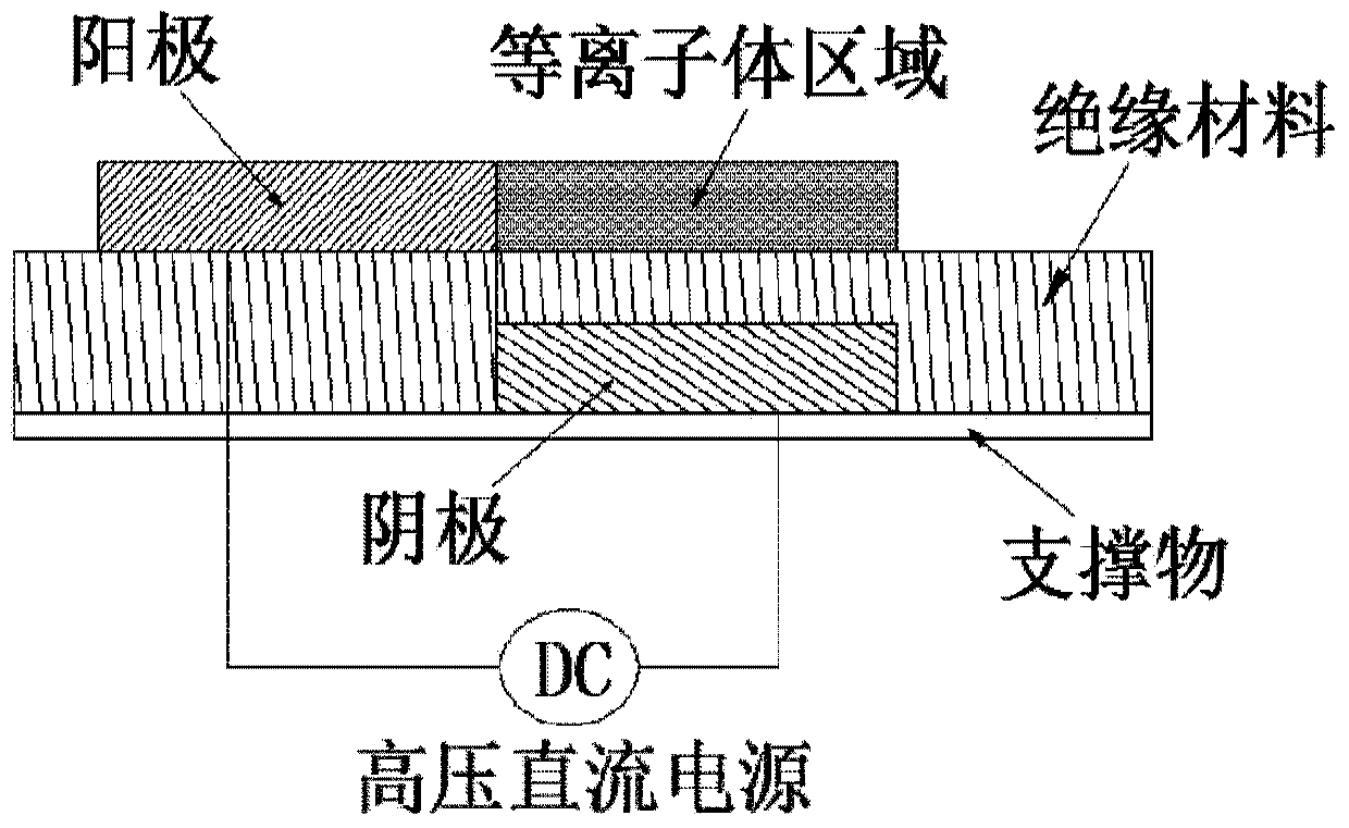
[0034] like figure 1 and figure 2 as shown, figure 1 It is a schematic diagram of a plasma flow display device based on the dielectric barrier discharge principle provided by the present invention, figure 2 Yes figure 1 The schematic diagram of the positional relations...


PUM


Abstract

The invention discloses a plasma flow visualization device based on a dielectric barrier discharge principle. The plasma flow visualization device comprises an insulating material serving as detected fluid, anodes arranged on the obverse side of the insulating material, cathodes arranged on the reverse side of the insulating material, a high-voltage direct current power supply used for applying voltage to the anodes and the cathodes, and a high-speed camera, wherein the anodes and the cathodes are arranged on the obverse side and the reverse side of the insulating material in a staggered mode; the high-speed camera is used for shooting changes, along with unsteady pressure distribution of the surface of the insulating material, of plasma area fluorescence intensity distribution and for visually displaying distribution and change rules of pressure on the surface of the insulating material. By the adoption of the plasma flow visualization device, the problems that existing flow visualization measuring equipment interferes with flow fields and tracer particles are poor in tracing are resolved, and the purpose that qualitative and quantitative analysis is carried out on a complex flow mechanism in an impeller machine is achieved.

Description

technical field [0001] The invention relates to the technical field of display and measurement of unsteady flow field on the wall surface of turbomachinery in aerospace technology, in particular to a plasma flow display device based on the principle of dielectric barrier discharge for displaying unsteady flow field on the inner wall surface of turbomachinery. Background technique [0002] Due to the complexity of the internal flow of the turbomachinery, it is embodied in: strong three-dimensionality, reverse pressure gradient, shock wave interference, aerodynamic instability, etc. These factors are mutually coupled and stimulated under the condition of following different nonlinear laws, and have always been the driving force behind the basic and applied research on the flow inside the compressor. In addition, with the continuous update of turbomachinery design methods, it has also developed from the early one-dimensional design to the current full three-dimensional unsteady...

Claims


Application Information

Patent Timeline
Patent Type & Authority Applications(China)
IPC IPC(8): G01M10/00
Inventor 李继超林峰李帆聂超群
Owner INST OF ENGINEERING THERMOPHYSICS - CHINESE ACAD OF SCI
Why Eureka
Try Eureka