Simple antenna far field test system and application thereof

A far-field test and antenna test stand technology, applied in the direction of electromagnetic field characteristics, etc., can solve the problems of long time required for antenna positioning and adjustment, and no device records, etc., to achieve convenient and fast adjustment, shorten adjustment time, and fix flat panel antenna quickly Effect

Inactive Publication Date: 2013-12-25
SHANDONG GUOWEI SHUNTAI SATELLITE COMM
View PDF4 Cites 14 Cited by
  • Summary
  • Abstract
  • Description
  • Claims
  • Application Information

AI Technical Summary

Problems solved by technology

The test system described in this patent document is a client computer system, but there is no record for the fixed device of the measured flat panel antenna
In the actual test process, the antenna needs to be positioned and adjusted. Due to the differe

Method used


Image

  • Simple antenna far field test system and application thereof
  • Simple antenna far field test system and application thereof
  • Simple antenna far field test system and application thereof

Examples


Embodiment 1

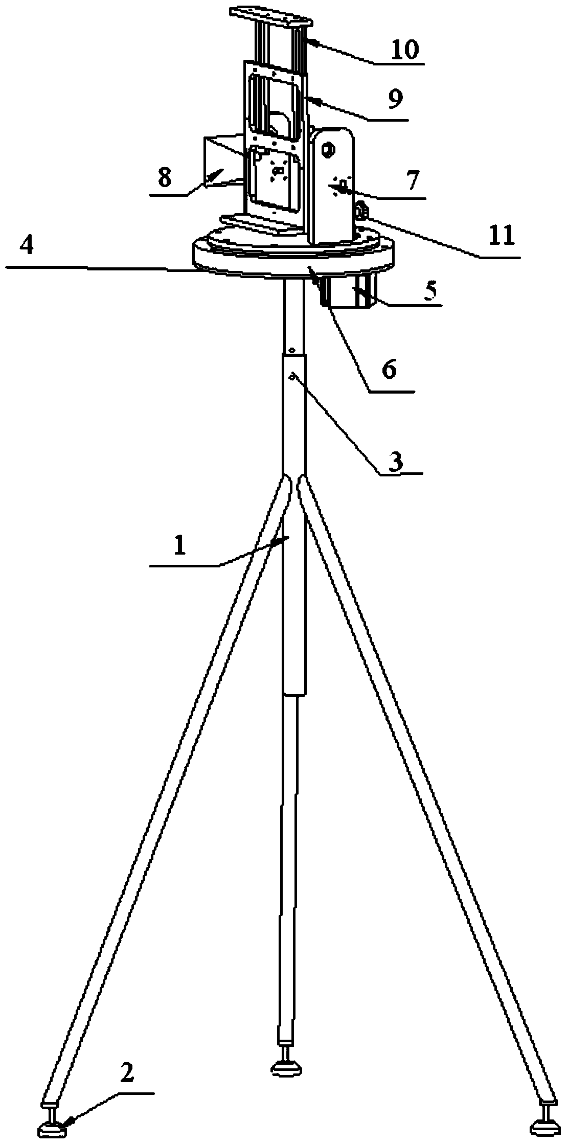
[0030] like Figure 1-3 shown.

[0031] A simple far-field test system for an antenna, including an antenna end and a horn end;

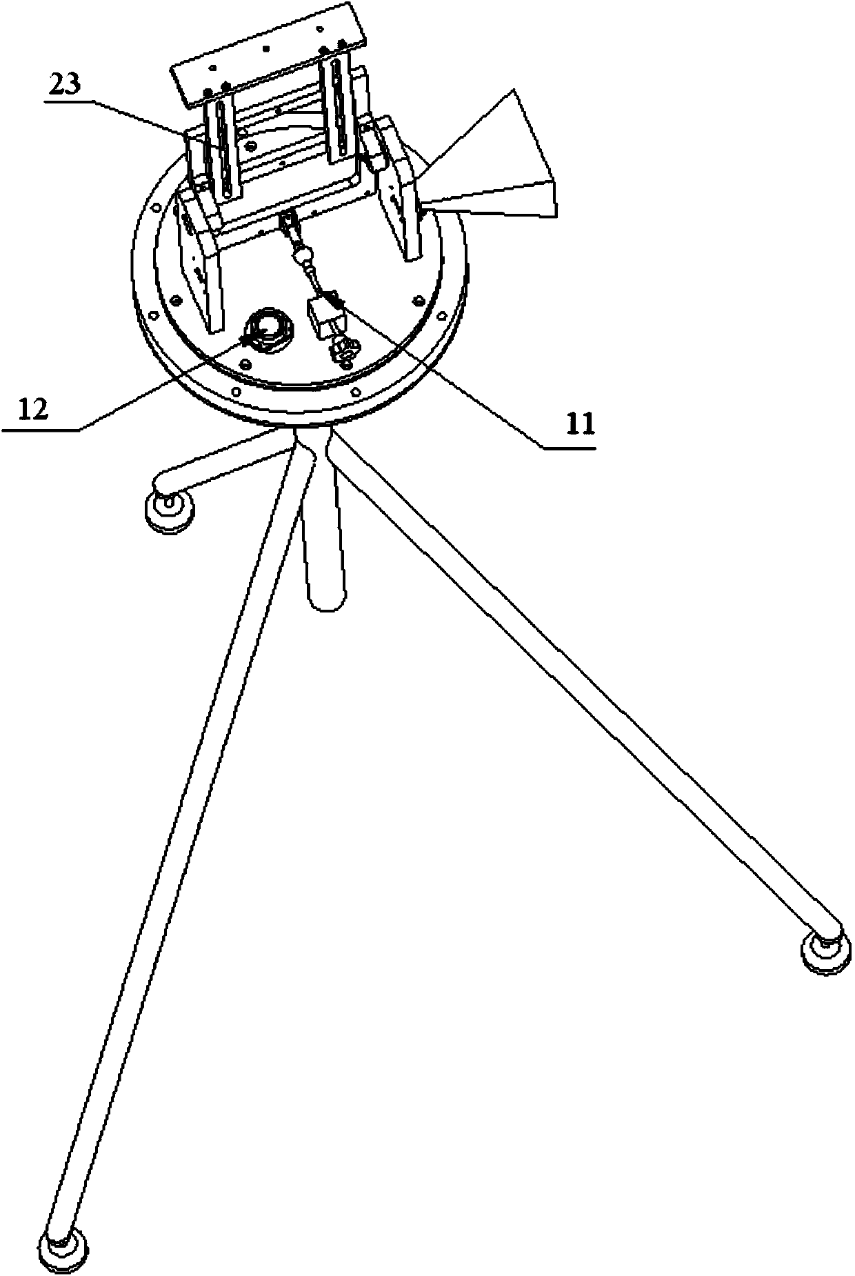
[0032] The antenna end includes a first tripod 1 and an antenna test stand 4, and the top of the first tripod 1 is movably connected with the antenna test stand 4 for adjusting the level of the antenna test stand 4 ; the bottom of the antenna test stand 4 is provided with a motor 5, on the antenna test stand 4 is provided with an antenna turntable 6 driven by the motor 5, and the antenna turntable 6 includes a slewing bearing, Antenna test stand 7, spirit level 12, antenna inclination angle fine-tuning bolt 11 and standard horn 8 arranged on one side of antenna test stand 7 arranged on the bearing; the bottom of described first tripod 1 is provided with level adjustment caster 2 ;

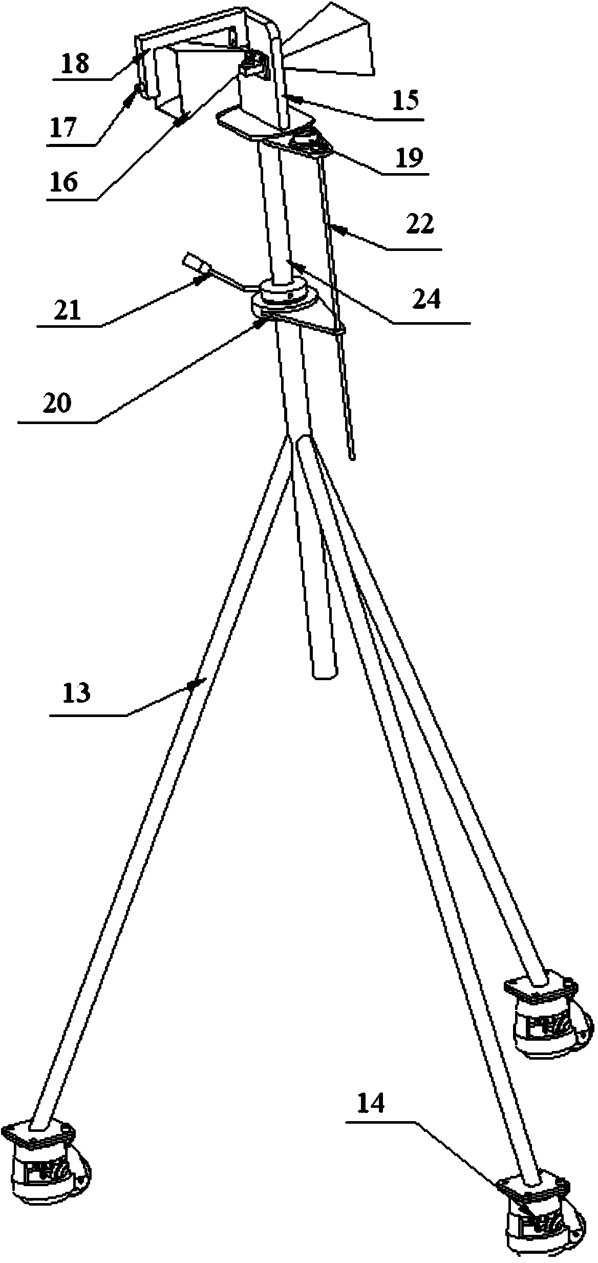
[0033] The horn end includes a second tripod 13 and a horn bracket 15, and the top of the second tripod 13 is connected with the horn bracket 15 by a screw 24 for adj...

Embodiment 2

[0038] A simple far-field test system for an antenna as described in Embodiment 1 is different in that a bearing seat 20 and a rotating handle 21 are provided on the top of the second tripod 13 at the horn end.

[0039] A limiting rod 22 is provided between the top end of the second tripod 13 at the horn end and the bottom end of the horn bracket 15 .

Embodiment 3

[0041] Utilize the method for testing panel antenna as described in embodiment 1-2 test system, comprise steps as follows:

[0042] (1) Horizontally align the standard gain horn 16 at the horn end and the standard horn 8 at the antenna end through the laser 17, the standard gain horn 16 at the horn end serves as a transmitting source, and the standard gain horn 8 at the antenna end serves as a receiving end, Write down the data, which is the relationship between the standard gain horn at the horn end and the standard horn at the antenna end in information communication;

[0043] (2) Fix the flat-panel antenna to be tested between the antenna support plate 9 and the antenna compression plate 10; the high-frequency head is installed at the square hole on the back of the flat-panel antenna;

[0044] (3) Fine-adjust the inclination angle of the panel antenna through the fine-tuning bolt 11, so that the panel antenna is perpendicular to the horizontal plane;

[0045] (4) Using the l...


PUM


Abstract

The invention discloses a simple antenna far field test system which comprises an antenna terminal an a horn terminal, wherein the antenna terminal comprises a first tripod and an antenna test board; the top of the first tripod is movably connected with the antenna test board; the bottom of the antenna test board is provided with a motor; the antenna test board is provided with an antenna revolving platform which is driven to rotate by the motor; the horn terminal comprises a second tripod and a horn bracket; the top of the second tripod is connected with the horn bracket by a screw rod; the horn bracket is provided with a gradienter, a standard gain horn and a laser; the laser is arranged at the front end of the standard gain horn. The simple antenna far field test system can be fixed aiming at antennae with different sizes and thus can be used many times; a flat plate antenna can be rapidly replaced and fixed by the simple antenna far field test system, so that a good hardware terminal is provided for the test and application of the flat plate antenna; the system can be used for locating the flat plate antenna quickly and is capable of greatly shortening the adjustment time and improving the test frequency of the flat plate antenna.

Description

technical field [0001] The invention relates to a simple far-field test system for antennas and its application, and belongs to the technical field of flat-panel antenna test devices. Background technique [0002] In the field of antenna research and development, far-field testing for antennas is a routine procedure for today's antenna testing. The current basic methods for measuring target scattering characteristics include far-field method, compact field method and near-field method. For the far-field method, let D be the maximum cross-sectional size of the target to be measured, and r be the distance between the transmitting antenna and the target to be measured, then when r≥2D2 / λ (λ is the wavelength), it can be approximately considered to be projected on the target to be measured Electromagnetic waves are plane electromagnetic waves. Similarly, the distance between the receiving antenna and the target to be measured should also meet this requirement, so that the receiv...

Claims


Application Information

Patent Timeline
IPC IPC(8): G01R29/08
Inventor 杨猛刘冰
Owner SHANDONG GUOWEI SHUNTAI SATELLITE COMM
Why Eureka
Try Eureka