
Radiosonde and method of upper-altitude wind detection based on ins

A detection method and radiosonde technology, which can be applied to instruments, measuring devices, scientific instruments, etc., can solve the problems of reduced wind measurement accuracy, large wind measurement errors, and difficulty in ensuring high-altitude wind detection heights, so as to meet the wind measurement accuracy requirements. Effect

Active Publication Date: 2016-08-10
PLA UNIV OF SCI & TECH
View PDF2 Cites 0 Cited by
  • Summary
  • Abstract
  • Description
  • Claims
  • Application Information

AI Technical Summary

Problems solved by technology

The detection of optical wind theodolite is easily affected by visibility and low clouds, and it is difficult to guarantee the detection height of high-altitude wind; the radio theodolite and wind radar system are complex, with large volume and weight, poor portability, and the error of wind measurement at low elevation angles is extremely large. The data cannot be used. In addition, the wind measurement radar must emit high-power electromagnetic waves for a long time, consumes a lot of power, and is likely to cause electromagnetic interference to other equipment; GNSS wind measurement accuracy is high, does not emit high-power electromagnetic waves, and its size and weight are small, but The system positioning depends on the existence and reliability of the space navigation constellation. When the satellite navigation signal encounters human interference, magnetic storms in the ionosphere, solar wind and other abnormalities will affect the positioning accuracy of the system, resulting in a decrease in wind measurement accuracy or even failure to measure wind

Method used


Image

  • Radiosonde and method of upper-altitude wind detection based on ins
  • Radiosonde and method of upper-altitude wind detection based on ins
  • Radiosonde and method of upper-altitude wind detection based on ins

Examples


Embodiment Construction

[0027] In order to better understand the technical content of the present invention, specific embodiments are given together with the attached drawings for description as follows.

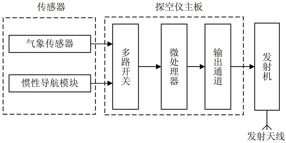
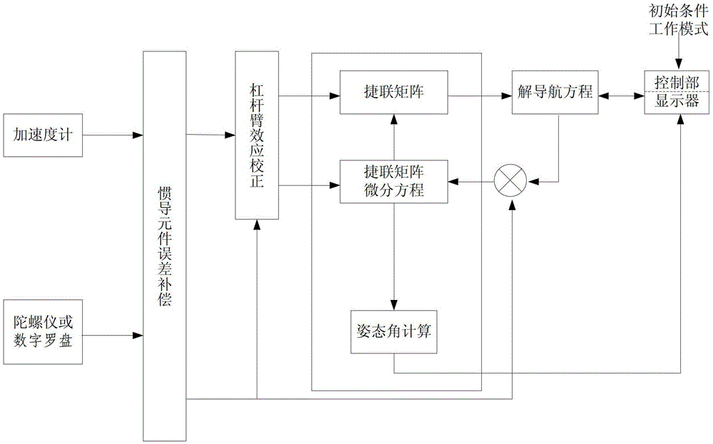
[0028] like Figure 1-3 As shown, according to a preferred embodiment of the present invention, a radiosonde, such as a radiosonde carried by a radiosonde balloon, includes a meteorological sensor, an inertial navigation module (INS), a radiosonde main board and a transmitter, wherein: Meteorological sensors are used to detect various meteorological elements in the air, such as temperature, pressure, humidity and other meteorological element values; the inertial navigation module is used to obtain the navigation parameters of the radiosonde; the main board of the radiosonde is connected with the aforementioned meteorological sensor and inertial navigation module signal It is also used to perform data quality processing, signal sampling transformation, and data stream generation of the aforementione...


PUM


Abstract

The invention provides a radiosonde and an INS-based high-altitude wind detection method, wherein the radiosonde includes a meteorological sensor, an inertial navigation module, a radiosonde main board and a transmitter, and the meteorological sensor is used to detect various meteorological elements in the air; the inertial The navigation module is used to obtain the navigation parameters of the radiosonde; the main board of the radiosonde is connected with the aforementioned meteorological sensor and the inertial navigation module signal and is used to perform data quality processing, signal sampling transformation and data flow generation of the aforementioned meteorological elements and navigation parameters, and will The data stream is transmitted to the transmitter; the transmitter receives the data stream transmitted by the main board of the radiosonde and transmits it. The radiosonde and the high-altitude wind detection method of the present invention realize positioning by setting an inertial navigation module in the radiosonde, the system is independent, does not cause electromagnetic interference to the outside world, and the wind measurement accuracy meets the current business requirements. Measurement provides a new and efficient way.

Description

technical field [0001] The invention relates to the technical field of high-altitude meteorological detection, in particular to a radiosonde and an INS-based high-altitude wind detection method. Background technique [0002] Upper-altitude wind detection in meteorological operations generally refers to the determination of the direction and speed of horizontal airflow at various heights from the ground to more than 30 kilometers in the air, that is, the determination of wind direction and wind speed. Real-time and accurate high-altitude wind detection data are the most basic data for weather analysis and forecasting, and are also the basic data for military meteorological support such as airdrops and airborne, artillery and air defense ballistic corrections. In meteorological operations, the trajectory of an object (usually a weather balloon or a balloon system composed of a weather balloon and a radiosonde) floating in the air is usually used to detect upper-altitude wind, ...

Claims


Application Information

Patent Timeline
Patent Type & Authority Patents(China)
IPC IPC(8): G01W1/08G01W1/02
Inventor 赵世军高太长陶冶周树道翟东力孙学金刘磊
Owner PLA UNIV OF SCI & TECH
Learn More