Simulation Method for Pressure Difference in Low Reynolds Number Incompressible Flow Over Curved Boundaries

A low Reynolds number, curved boundary technology, applied in the field of computer simulation, can solve problems such as pressure difference

Inactive Publication Date: 2017-02-08
WUZHOU UNIV
View PDF1 Cites 0 Cited by
  • Summary
  • Abstract
  • Description
  • Claims
  • Application Information

AI Technical Summary

Problems solved by technology

[0005] The purpose of the present invention is to provide a simulation method for the pressure difference in the low Reynolds number incompressible flow on the curved boundary in view of the technical problem that the prior art cannot handle the pressure difference in the low Reynolds number incompressible flow on the curved boundary

Method used


Image

  • Simulation Method for Pressure Difference in Low Reynolds Number Incompressible Flow Over Curved Boundaries
  • Simulation Method for Pressure Difference in Low Reynolds Number Incompressible Flow Over Curved Boundaries
  • Simulation Method for Pressure Difference in Low Reynolds Number Incompressible Flow Over Curved Boundaries

Examples


Embodiment 1

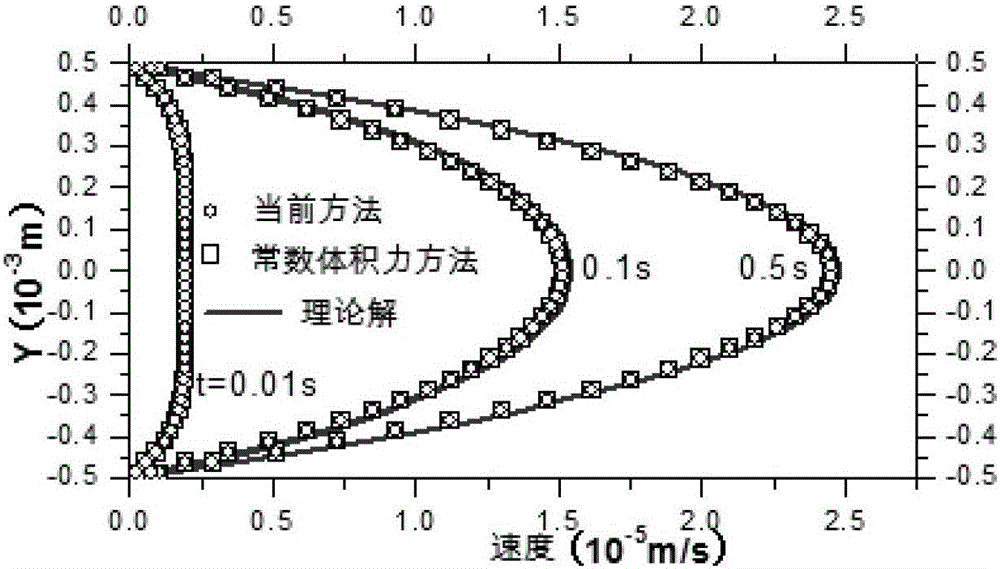
[0086] This embodiment adopts Poiseuille flow, that is, two infinite plates are respectively placed at coordinates y=-0.5YL and y=0.5YL, wherein YL is the distance between the two plates. Its initially stationary fluid is driven by a body force F (corresponding to the pressure difference between the inlet and outlet) parallel to the X-axis, and will eventually reach a steady state.

[0087] In this embodiment, YL=10 -3 m, the flow field length is d=5×10 -4 m, the hydrostatic pressure difference is △p =10 -4 N / m 2 , the simulation results of formula (1), formula (2) and formula (3) are as follows image 3 shown, and from image 3 It can be seen that the method of the present invention is consistent with the simulation results using constant body force, and both agree well with the theoretical solution.

Embodiment 2

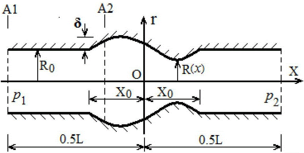
[0089] This embodiment adopts local expansion pipe flow, such as Figure 4 As shown, an axisymmetric blood vessel can be considered, and its pressure difference drives the fluid to flow in the pipeline, and the pressure difference is △p= p 1 -p 2 = 1.939006287×10 -3 N / m 2 , the radius of the pipe is a function of the position x, which can be expressed as (4):

[0090] R R 0 = 1 | x | > X 0 1 + δ 2 R 0 ( 1 + cos ...

Embodiment 3

[0094] The present embodiment adopts inclined plate flow, such as Figure 7 As shown, in this example, d BC =4mm, 2l 1 =0.5mm, α=3.503°, and the hydrostatic pressure difference between B and C is △p =1.21665968×10 -3 N / m 2 .

[0095] Using the method of the present invention, the simulation results of the horizontal velocity of the fluid particles along the X axis are as follows: Figure 8 shown; from Figure 8 As can be seen in the figure, the simulation results using the method of the present invention are again in agreement with the theoretical solution, but not in the case of constant body force.


PUM


Abstract

The invention relates to a simulation method of pressure difference in low Reynolds number incompressible flow at bending boundaries. The method comprises the following steps of S1, enabling a calculation module to determine if the formula (1) is met or not for the given low Reynolds number incompressible flow, or R0<<x0, L>>R0, Re<1; S2, if the formula (1) in the step S1 is met, enabling the calculation module to generate or inherit particles in a simulation flow field, and adopting a multi-boundary tangential technology to process the fixed-wall boundary and generating virtual particles according to the requirement of the technology; S3, enabling the calculation module to calculate the volume force FA2 of each particle at the x point of any position according to the formula (2), and calculating the volume force FA1 at an inlet by the formula (3); S4, enabling an output module to output the volume force FA2 at the x point in the step S3. The method can conveniently convert the pressure difference in the low Reynolds number incompressible flow at the bending boundaries into the volume force at any part.

Description

technical field [0001] The invention relates to the technical field of computer simulation, and more specifically relates to a simulation method for pressure difference in low Reynolds number incompressible flow on a curved boundary. Background technique [0002] When applying Smoothed Particle Hydrodynamics (SPH) to simulate low Reynolds number incompressible flow, it is very important to solve the pressure gradient driving the fluid motion, because the pressure is only expressed as a gradient in the Navier-Stokes equation. In the Weakly Compressible SPH (WCSPH) algorithm, the total pressure is usually decomposed into dynamic pressure and hydrostatic pressure, so the gradient of the total pressure can be obtained through the gradient of these two pressures. [0003] For the WCSPH method, modeling the dynamic pressure gradient is simple and straightforward, while the hydrostatic pressure gradient is usually considered as a body force. Morris used WCSPH to study low Reynolds...

Claims


Application Information

Patent Timeline
Patent Type & Authority Patents(China)
IPC IPC(8): G06F17/50
Inventor 梁朝湘张超英刘海燕黄寄洪冀肖榆时伟
Owner WUZHOU UNIV
Why Eureka
Try Eureka