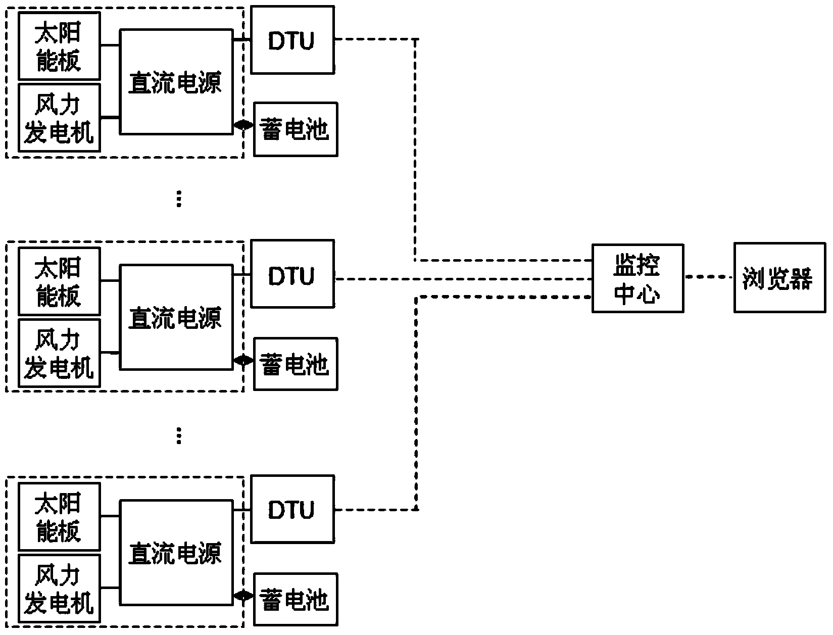
[0040] figure 1 It is a structural schematic diagram of an embodiment of the DC power supply system for realizing remote meter reading and monitoring of the present invention. like figure 1 As shown, a DC power supply system for remote meter reading and monitoring of the present invention includes a DC power supply system for supplying power to DC loads, and a data transmission unit (ie, figure 1 The DTU in the DTU) and the monitoring center that communicates with the data transmission unit. Taking the DC power supply system of a communication base station as an example, the technical solution of the present invention is described as follows.
[0041] The DC power supply system includes a power generation component, a DC power supply, and a storage battery. The electric energy generated by the power generation component is stored in the battery through the DC power supply. The DC power supply has a DC energy meter. In this embodiment, the DC power supply is the communication station of the communication base station. power supply. The power generation component is a wind generator and/or a solar panel. In this embodiment, the power generation component is a wind generator and a solar panel, that is, a wind-solar hybrid power generation method is adopted. The wind generator converts the natural wind energy into electrical energy, which is stored in the battery through the DC power supply. The solar panel converts natural light energy into electrical energy, which is stored in the battery through a DC power supply. The DC electric energy meter provides power generation metering and monitoring functions for the DC power supply system. The power generation metering functions include cumulative power generation, working voltage, working current, etc., and the monitoring functions include voltage alarms, power alarms, etc. The storage battery is -48V direct current, and supplies power for direct current loads such as communication equipment of the communication base station.
[0042] The data transmission unit is communicatively connected with both the DC electric energy meter and the monitoring center. In this embodiment, the number of data transmission units is the same as that of the DC energy meters and is connected to the DC energy meters in a one-to-one correspondence, that is, each data transmission unit communicates with the monitoring center independently. Of course, in other implementations In the example, it is also possible that a data transmission unit is connected with multiple DC electric energy meters. When the scale of the communication base station is large, there may be situations where multiple DC power supply systems supply power at the same time. In this embodiment, the data transmission unit can be any one of GPRS DTU, CDMA DTU and 3G DTU, and the data transmission unit is connected to the DC electric energy meter through the RS485 serial interface, and supports the MODBUS communication protocol. Of course, the data transmission unit and the DC electric energy meter may also be connected through other interfaces.
[0043] The monitoring center includes a server, a database, and a remote meter reading and monitoring module, the remote meter reading and monitoring module sends a meter reading instruction to the DC electric energy meter through the data transmission unit, and the remote meter reading and monitoring module also receives the According to the meter reading instructions received by the DC electric energy meter, the data sent by the data transmission unit is stored in the database, and the remote meter reading and monitoring module is set after sending the meter reading instructions of the set times When the data sent by the DC electric energy meter is not received within a specified time, a warning message of meter reading failure is generated. In this embodiment, the data transmission unit and the monitoring center are connected by wireless communication, and the two can be connected through the Internet, and of course they can also be connected through other methods. The monitoring center is responsible for the functions of remote meter reading and monitoring, as well as the analysis and statistics of remote meter reading data, such as generating daily power generation reports, monthly power generation A variety of ways to provide users with the realization of remote meter reading and monitoring, analysis and statistics functions.
[0044]The DC power supply system for remote meter reading and monitoring of the present invention can conveniently and quickly perform power generation measurement, monitoring and maintenance for a large number of decentralized DC power supplies, saving a lot of manpower and material resources.
[0045] Preferably, the DC power supply system for realizing remote meter reading and monitoring further includes a browser connected to the monitoring center through a network. Users can use this system through the browsers of computers and mobile phones, and the monitoring center can automatically notify users to deal with it in time through various methods such as text messages, telephone calls, and emails.
[0046] The present invention also provides a method for realizing remote meter reading and monitoring, using the DC power supply system for remote meter reading and monitoring as described above to perform remote meter reading and monitoring, such as figure 2 shown, including the following steps:
[0047] The remote meter reading and monitoring module of the monitoring center sends a meter reading command to the DC energy meter of the DC power supply system through the data transmission unit, and waits for the data to return;
[0048] If the monitoring center receives the returned data within the set time, it will write the received meter reading data to the database table for storage;
[0049] If the monitoring center does not receive the return data within the set time, it will resend the meter reading command until the return data is received;
[0050] If the number of times of sending meter reading instructions reaches the set maximum value and the return data is still not received within the set time, a warning message of meter reading failure will be generated. The maximum value set is 3 times in this embodiment, and it can also be changed within a certain range, such as 1 to 5 times.
[0051] Through the above method, the staff can conveniently and quickly realize the remote meter reading and monitoring operation of the DC power supply of the communication base station or other facilities in the monitoring center. The remote meter reading and monitoring program runs no less than once a day, and can be multiple times. The first run time of each day is as close as possible to the start time of the day at 00:00.
[0052] Preferably, the monitoring center sends the warning information of meter reading failure to the browser, that is, informs the user, so that even if the user is not in front of the monitoring center, the user can be informed of the meter reading failure information in time.
[0053] As preferably, said method also comprises the following steps:
[0054] After receiving the returned data, the monitoring center judges whether the meter reading data is the first data received from the DC power supply;
[0055] If not, then the cumulative power generation, meter reading time, and date are written to the power generation daily data table for preservation, the type field of the power generation daily data table is set to the first character, and the meter reading times field is set to the actual meter reading times of the day;
[0056] If so, then write the cumulative power generation, meter reading time, and date to the daily power generation data table for storage, and set the type field of the daily power generation data table to the second character, and the second character is different from the first character, and the meter reading The count field is set to empty.
[0057] For example, the type field of the power generation daily report can have two values, 0 and 1. 0 is the first character, indicating that it is the first meter reading, and 1 is the second character, indicating that it is not the first time meter reading. Of course, in other embodiments, it is also possible to use other two values to indicate, for example, "yes" indicates that it is the first time meter reading, and "no" indicates that it is not the first time meter reading. Another example is to use "Y" to indicate that it is the first time to read the meter, and to use "N" to indicate that it is not the first time to read the meter. For another example, it can also be agreed to use any two characters that are not the same to represent.
[0058] Through the above preferred solution, the user can obtain a daily report of the power generation, and can intuitively and accurately understand the power generation of the DC power supply.
[0059] As a preferred solution, the monitoring center checks whether there is voltage alarm and/or power alarm in the received meter reading data;
[0060] If so, write the voltage alarm and/or power alarm to the database table for preservation, and generate alarm information;
[0061] If not, then end the meter reading normally.
[0062] Through the above preferred solution, the user can obtain the abnormal situation of the DC power supply system, so as to take processing measures in time.
[0063] Preferably, the monitoring center sends the generated alarm information to the browser, so as to timely notify the user of the abnormal situation of the DC power supply system.
[0064] As a preferred solution, such as image 3 As shown, the above method also includes the following steps:
[0065] The monitoring center checks the daily report of power generation according to the month;
[0066] Obtain the accumulative power generation and meter reading time of the first and last meter readings of the DC power supply in the month, and calculate the monthly power generation by subtracting the accumulative power generation of the last meter reading in the month from the accumulative power generation of the first meter reading in the month, write To the monthly report data table of power generation;
[0067] Generate monthly power generation reports and output them to the browser.
[0068] The above solutions allow users to intuitively and conveniently understand the power generation of the DC power system in any month.
[0069] As a preferred solution, such as image 3 As shown, the above method also includes the following steps:
[0070] The monitoring center determines the electricity price and billable power generation and calculates the electricity fee;
[0071] Write the power generation, billing power generation, electricity price and electricity fee to the power generation billing monthly report data table;
[0072] Generate electricity billing monthly report and output to browser.
[0073] The above solutions enable users to intuitively and conveniently understand the billing situation of the power generation of the DC power system in any month, which facilitates the settlement of electricity bills.
[0074] Example 1: Remote meter reading under normal conditions
[0075] The monitoring center receives the remote meter reading of DC power supply system A within a period of time, as shown in the table below.
[0076]
[0077] Then, the daily power generation capacity of the DC power supply system A can be obtained, as shown in the table below.
[0078]
[0079]
[0080] Then, the monthly report of power generation of DC power system A can be obtained, as shown in the table below.
[0081]
[0082] Then, the monthly billing report of power generation of DC power system A can also be obtained, as shown in the table below.
[0083] serial number
[0084] Example 2: Remote meter reading with meter reading failure
[0085] The monitoring center 3 receives the remote meter reading of the DC power supply system B within a period of time, as shown in the table below. Among them, the meter reading failed for two consecutive days on the 2nd and 3rd.
[0086]
[0087] Then, the daily power generation capacity of DC power system B can be obtained, as shown in the table below.
[0088]
[0089] Then, the monthly report of power generation of DC power system B can be obtained, as shown in the table below.
[0090]
[0091] Then, the monthly billing report of power generation of DC power system B can also be obtained, as shown in the table below.
[0092] serial number
[0093] The above is the processing of the power generation report and the monthly billing report of power generation, and the failure of meter reading on February 2 and February 3 is handled as follows:
[0094] Failed meter reading on February 2: first generate a meter reading failure warning and send it to the browser. The format of meter reading failure warning is: warning type + DC power system name + receiving time. For example, the warning of meter reading failure is [Meter Reading Failure: Qingshidun, January 1, 2013 03:21], indicating that the warning type is "Meter Reading Failure", the name of the DC power system is "Qingshidun", and the receiving time is January 1, 2013 at 03:21.
[0095] Meter reading failed on February 3: similar, no repeat.
[0096] Example 3: Remote meter reading with voltage alarm and power alarm
[0097] The monitoring center 3 receives the remote meter reading of the DC power supply system C within a period of time. Among them, voltage alarms and/or power alarms occurred several times on the 13th.
[0098] When a voltage alarm and/or power alarm is detected, the alarm data is first written to the database table for storage, and then an alarm is generated and sent to the browser. The format of voltage alarm and/or power alarm is: alarm type + alarm value + DC power system name + receiving time. For example, the voltage alarm is [low voltage alarm: 50.14V, Qingshidun, February 13, 2013 03:21], indicating that the alarm type is "low voltage alarm", the alarm value is "50.14V", and the DC power system name It is "Qingshidun", and the reception time is 03:21 on February 13, 2013.
[0099] There are three alarm types: low voltage alarm, high voltage alarm, and low power alarm.
[0100] Example 4: Remote meter reading with multiple DC power sources
[0101] The monitoring center 3 receives the remote meter readings of the DC power systems A, B, and C within a period of time, see examples 1, 2, and 3. Then these three DC power supply systems can be combined to form a monthly report of power generation and a monthly report of power generation billing, as follows.
[0102] The following table is the monthly report of the power generation of DC power systems A, B, and C.
[0103]
[0104] The following table is the monthly billing report of power generation of DC power supply systems A, B, and C.
[0105]
[0106] The above embodiments are only exemplary embodiments of the present invention, and are not intended to limit the present invention, and the protection scope of the present invention is defined by the claims. Various modifications or equivalent replacements made to the present invention by those skilled in the art within the spirit and protection scope of the present invention also fall within the protection scope of the present invention.