Output amplifier

A technology for amplifiers and signal output terminals, applied in the field of power output amplifiers, can solve problems such as low work efficiency, achieve the effects of convenient application, prevent crossover distortion, and increase gain

Inactive Publication Date: 2013-12-25
KUNSHAN XINJINFU PRECISION ELECTRONICS
View PDF4 Cites 3 Cited by
  • Summary
  • Abstract
  • Description
  • Claims
  • Application Information

AI Technical Summary

Problems solved by technology

When the load increases to a certain level, the output power decreases, the output signal is nonlinearly distorted, and its working efficiency is low

Method used


Image

  • Output amplifier

Examples


Embodiment Construction

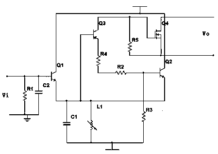
[0013] Such as figure 1 As shown, the present invention includes a triode and a field effect transistor. The base of the first triode Q1 is used as a signal output terminal, and its emitter is connected to a negative voltage through the first resistor C1. The two ends of the first resistor C1 are connected in parallel with a variable voltage Inductor L1; the emitter of the first transistor Q1 is connected to the emitter of the second transistor Q2, and the collectors of both are connected to a positive voltage, and the base of the second transistor Q2 passes through the second resistor R2 and The series connection of the fourth resistor R4 is connected to the emitter of the third transistor Q3, the base of the third transistor Q3 is connected to the emitter of the first transistor Q1, and its collector is connected to the gate of the field effect transistor Q4 The drain and source of field effect transistor Q4 constitute the signal output terminal.

[0014] The base of the se...


PUM


Abstract

The invention discloses an output amplifier comprising transistors and a field-effect transistor. A base of a first transistor serves as a signal output end, and a drain electrode and a source electrode of the field-effect transistor form a signal output end. The first transistor and a second transistor form a differential input electrode and a third transistor forms a high-gain intermediate amplifier to prevent signals from generating crossover distortion so as to influence output signal power. Negative feedback is utilized to increase gain, output power is large and application is convenient.

Description

[0001] technical field [0002] The invention relates to an amplifier, in particular to a power output amplifier. Background technique [0003] The function of the power amplifier is to provide a certain output power to the load speaker of the audio amplifier. When the load increases to a certain level, the output power decreases, the output signal is nonlinearly distorted, and its working efficiency is low. [0004] Therefore need a kind of new technical scheme to solve the above problems. Contents of the invention [0005] Purpose of the invention: In view of the problems and deficiencies in the above-mentioned prior art, the purpose of the invention is to provide a power output amplifier with large output power and stable performance. [0006] Technical solution: The technical solution adopted in the present invention is an output amplifier, including a triode and a field effect transistor, the base of the first triode is used as a signal output terminal, and its emit...

Claims


Application Information

Patent Timeline
Patent Type & Authority Applications(China)
IPC IPC(8): H03F3/20H03F1/32
Inventor 王火明
Owner KUNSHAN XINJINFU PRECISION ELECTRONICS
Why Eureka
Try Eureka