Supercharge Your Innovation With Domain-Expert AI Agents!

Surface covering kit comprising panels and an extraneous locking element

A technology for surface covering and locking elements, applied in the field of ceiling or wall coverings, floors, can solve the problems of difficult insertion, expensive and waste of wedge-shaped connecting elements, and achieve the effect of ease of use

Inactive Publication Date: 2013-12-25
AITE CONSULTING CO LTD
View PDF11 Cites 4 Cited by
  • Summary
  • Abstract
  • Description
  • Claims
  • Application Information

AI Technical Summary

Problems solved by technology

[0008] Milling tools used for such complex profiles with multiple surfaces are expensive to maintain over time because the necessary tight tolerances cannot be met if the milling tool wears over time
Periodic maintenance and replacement of tools and shutdowns for maintenance of production equipment are also costly
[0009] According to the above description, in order to mill such a profile on the lateral sides, a portion of the panel material is milled off and is wasted if it cannot be easily recycled
In the case of mostly wood-based materials such as MDF, HDF, particleboard and OSB boards, not only is the wood material wasted, but the components of chemical adhesives (resins, etc.) combustible dust
[0010] Another disadvantage of this prior art is that such complex contours cannot be employed on relatively thin panels
With such a tongue and groove system on the lateral sides, long thin rods are left at the short ends of the panels which can be easily damaged or broken during transport and installation
[0011] Another disadvantage of the prior art described above is that this profile requires a certain amount of overlap on the lateral sides of the two panels
A further consequence of this complex profile may also be a relatively large number of defective products
As with other prior art mentioned above, its production is quite complex and expensive
[0014] A further disadvantage of DE'016 is that the disclosed wedge connection element may be difficult to insert into its groove due to friction
This profile can be achieved by broaching according to EP'670 or by laser cutting, both methods known to be tedious, slow and expensive
The unique profile mentioned in EP'670, which can be achieved by traditional methods such as milling, is not very suitable for reliable connection

Method used


Image

  • Surface covering kit comprising panels and an extraneous locking element
  • Surface covering kit comprising panels and an extraneous locking element
  • Surface covering kit comprising panels and an extraneous locking element

Examples


Embodiment Construction

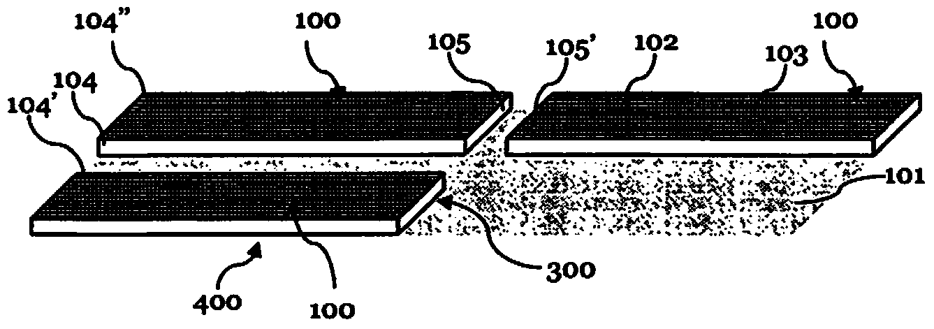
[0082] figure 1 is a schematic diagram showing three exemplary panels 100 laid in a common plane 101 . These panels 100 can be made of any suitable material, however the invention is particularly suitable for laminate panels consisting of HDF (High Density Fibreboard), MDF (Medium Density Fibreboard) or LDF (Low Density Fibreboard). The panel 100 can also be made of wood composite, solid wood, plywood, particle board or OSB (oriented strand board). The panel 100 has an average or mean thickness of between 3mm and 30mm and most preferably between 4mm and 14mm. Due to this simple geometry of the connection elements according to the invention on the lateral sides, they are especially suitable for very thin panels, such as 5 mm flooring laminates.

[0083] The decoration 103 can be provided as a separate decoration layer, for example a decoration printed on paper, or can also be printed directly on the panel 100 . The decoration 103 can be, for example, imitation solid wood, im...


PUM


Abstract

A surface covering kit is disclosed, comprising a plurality of generally rectangular panels (100). Each panel is provided with grooves (301, 302, 301', 302') forming an insertion channel (303) when two panels (100) are laid next to each other along their transverse sides (105, 105') in a common laying plane (101). An extraneous locking element (210) is received by the insertion channel (303), the extraneous locking element (210) having a longitudinal dimension and a cross-section perpendicular to said longitudinal dimension which forms a cross with at least four cross arms. The corresponding cross arms of the insertion channel have two parallel flank surfaces (1603, 1604) each, and each of the cross arms is oriented diagonally in a plane perpendicular to the panel plane (102).

Description

technical field [0001] The present invention relates to a surface covering, in particular to a floor, ceiling or wall covering comprising a panel comprising a laminate flooring panel and an external locking element. Background technique [0002] In the prior art, many different types of surface coverings, in particular floor, ceiling or wall coverings, are known. Rectangular panels, sometimes having the appearance of wood panels or tiles, are quite common, especially for interior applications. [0003] Such panels are often provided with trim on one side, for example to replicate the look of a solid wood panel. This decoration can be provided as a printed paper layer or veneer, or it can be printed directly on the carrier sheet. Typically these panels are rectangular and can be coupled to each other using complementary coupling means, usually formed as an integral part at the sides of the panels. Thus, similar panels can be joined at respective adjacent sides to form eg a...

Claims


Application Information

Patent Timeline
Patent Type & Authority Applications(China)
IPC IPC(8): E04F13/08E04F15/02F16B5/00
CPCE04F13/08E04F15/02E04F2201/0153E04F2201/0169E04F2201/0529E04F2201/0541E04F2201/057E04F2201/0576E04F2201/0582F16B5/0052F16B5/0012F16B5/008E04F13/0894
Inventor 汉内斯·斯派德尔埃迪·鲍茨卡
Owner AITE CONSULTING CO LTD
Features
  • R&D
  • Intellectual Property
  • Life Sciences
  • Materials
  • Tech Scout
  • Unparalleled Data Quality
  • Higher Quality Content
  • 60% Fewer Hallucinations
Learn More