High-speed vortex electric field and cyclone combined separation method and cyclone separator

A cyclone separator and cyclone separation technology, applied in the direction of cyclone devices, etc., can solve the problems of long ionization adsorption channel, secondary flying of plate dust, and the inlet air velocity cannot be too high, and achieve the effect of good separation effect.

Inactive Publication Date: 2014-01-01
JIANGSU UNIV
View PDF8 Cites 18 Cited by
  • Summary
  • Abstract
  • Description
  • Claims
  • Application Information

AI Technical Summary

Problems solved by technology

[0006] The previous electrostatic adsorption technology combines the ionization electric field and the adsorption separation electric field into one, but the electrostatic adsorption has the following defects: ① the inlet air velocit

Method used


Image

  • High-speed vortex electric field and cyclone combined separation method and cyclone separator
  • High-speed vortex electric field and cyclone combined separation method and cyclone separator
  • High-speed vortex electric field and cyclone combined separation method and cyclone separator

Examples


Example Embodiment

[0018] The present invention will be further described in detail below in conjunction with the drawings and specific embodiments:

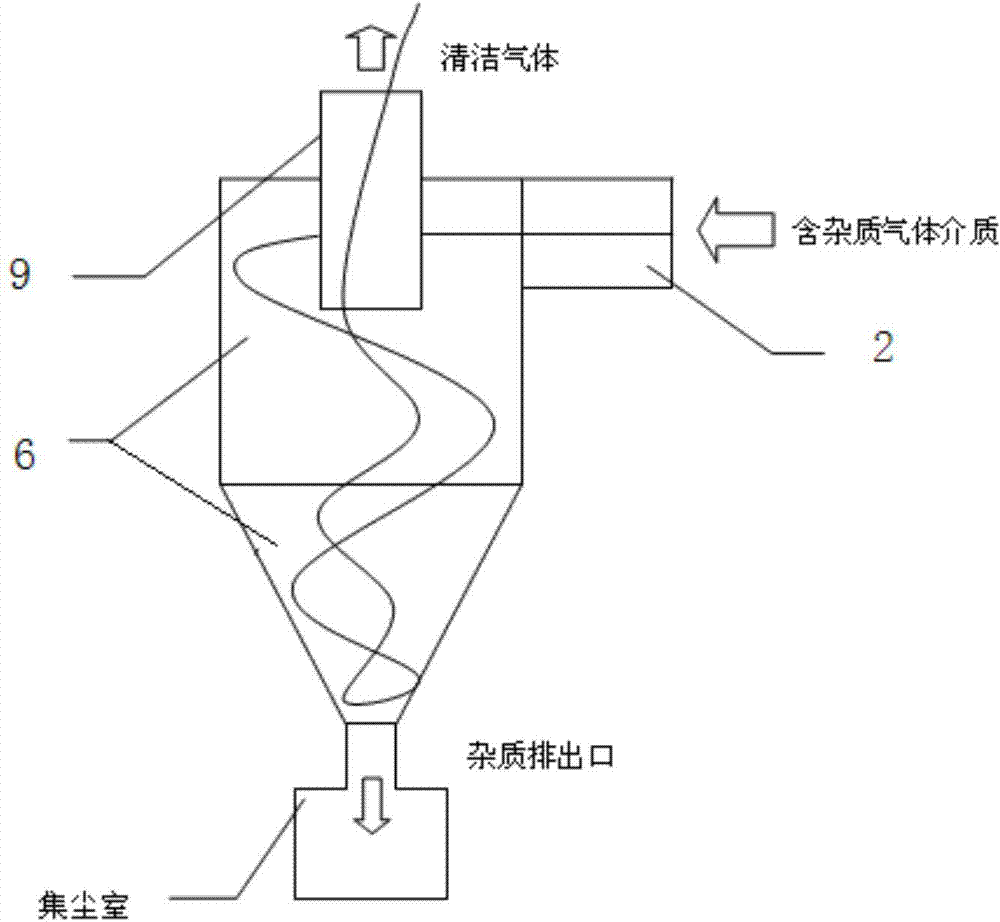
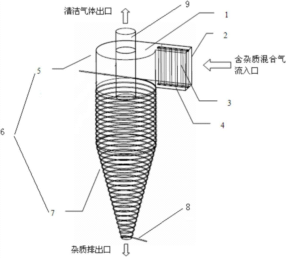
[0019] Such as figure 2 As shown, the cyclone separator body 1 is composed of an inlet section 2, a separation section 6 and an exhaust pipe 9, and the bottom of the separation section 6 is an impurity discharge outlet. The outer side of the inlet section 2 is provided with a pole plate 4, and the middle is a corona pole 3; the separation section 6 is divided into a metal section 5 in the upper half and an insulating section 7 in the lower half. The surface of the insulating section 7 is wound with a coil to form a solenoid ; The exhaust pipe 9 is arranged in the middle of the metal section 5 to form an annular air flow channel.

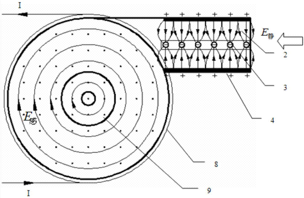
[0020] Such as image 3 As shown, the impurity-containing airflow enters the cyclone separator at a speed of 5-8m / s, the pole plate 4 of the inlet section 2 is connected to the positive pole of the high-voltage DC power supp...


PUM


Abstract

The invention relates to a high-speed vortex electric field and cyclone combined separation method and a cyclone separator. The method comprises the following steps: two electric fields independent from each other are arranged in the cyclone separator, an entrance section is used as an electrostatic field, and a separation section is used as a vortex electric field; an air flow containing impurities passes through the electrostatic field at the entrance section formed by a plate electrode and a corona electrode, and enters the vortex electric field at the separation section, impurity particles are ionized in the electrostatic field, electrified particles rotate at an accelerated speed in the vortex electric field under the combined action of the lorentz force and the electric field force, and the impurities impact the wall surface to be separated in a gathering manner through adjusting the electric field parameters. Compared with the traditional cyclone separator, the cyclone separator provided by the invention, can achieve better separating effect.

Description

technical field [0001] The invention relates to a high-speed vortex electric field cyclone separation method and a cyclone separator, in particular to a composite separation technology and device combining electric field separation and cyclone separation. Background technique [0002] In industrial production, cyclone separators are often used for gas-solid-liquid separation in places where a large amount of dust is generated or where solid particles and liquid droplets carried in the transport gas need to be removed as much as possible. The cyclone separator has the following advantages: ① no moving parts, reliable and safe operation; ② low maintenance cost, simple and convenient daily maintenance; The better the separation. [0003] figure 1 It is a structural diagram of a general cyclone separator, including the inlet section 2, the separation section 6, the exhaust pipe 9 and the impurity discharge port at the bottom of the separation section; the upper part of the sep...

Claims


Application Information

Patent Timeline
IPC IPC(8): B04C9/00
Inventor 裴宏杰郑文杰王贵成沈春根陶春鸣
Owner JIANGSU UNIV
Why Eureka
Try Eureka