A conveying mechanism for a car door
What is Al technical title?
Al technical title is built by PatSnap Al team. It summarizes the technical point description of the patent document.
A technology for conveying mechanisms and automobile doors, which is applied in the direction of conveyors, conveyor objects, mechanical conveyors, etc., can solve problems affecting the overall shape of the body-in-white, hidden dangers of workers' car doors, and high labor intensity of workers, so as to achieve small space occupation, Reduce labor intensity and high degree of automation
Active Publication Date: 2016-01-06
烟台宇信科技有限公司
View PDF11 Cites 0 Cited by
Summary
Abstract
Description
Claims
Application Information
AI Technical Summary
This helps you quickly interpret patents by identifying the three key elements:
Problems solved by technology
Method used
Benefits of technology
Problems solved by technology
At present, in the automobile welding process, the hemming of the automobile door is usually manually transported to the press for hemming. During the transportation, at least two workers are required to lift the door down from the horizontal state of the previous station, and then lift it onto the press. The defects are as follows. First, the work efficiency in the handling process is low, and the labor intensity of the workers is high. Secondly, due to the high table top of the press, it cannot be positioned accurately, which poses a certain safety hazard to both the workers and the car door. Deformation directly affects the overall shape of the entire body-in-white and increases production costs
Method used
Image
Click on the blue label to locate the original text in one second.
Reading with bidirectional positioning of images and text.
Examples
Embodiment Construction
[0027] The principles and features of the present invention are described below in conjunction with the accompanying drawings, and the examples given are only used to explain the present invention, and are not intended to limit the scope of the present invention.
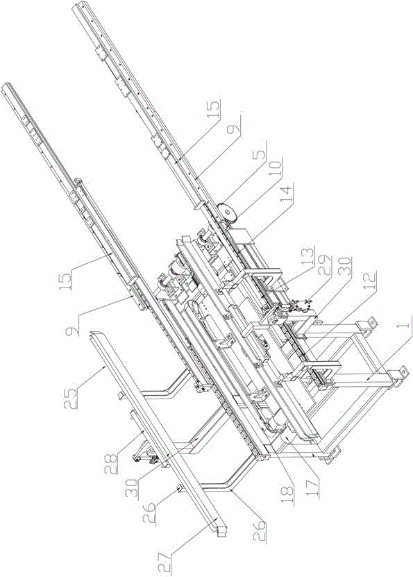
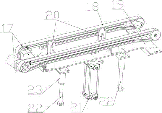
[0028] Such as Figure 1 to Figure 6 As shown, a conveying mechanism for an automobile door includes an underframe 1, a conveying mechanism, a transfer mechanism 2 and a guide mechanism 24 arranged on the underframe, and it is characterized in that a jacking mechanism is provided at the bottom of the conveying mechanism , the guide mechanism 24 is symmetrically arranged on both sides of the transmission mechanism and fixed on the chassis 1;
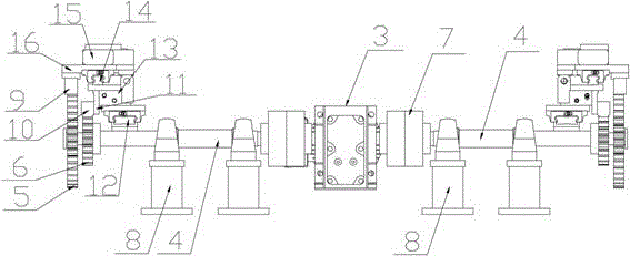
[0029] Described transfer mechanism 2 comprises double-layer slide rail, motor 3 and the transmission shaft 4 that is arranged on described motor 3 two ends, bull gear 5, pinion 6, and described motor 3 is connected with one end of transmission shaft 4 by coupling 7 , the othe...
PUM
Abstract
The invention relates to a conveying mechanism of an automobile door and belongs to the technical field of automobile manufacturing. The conveying mechanism of the automobile door comprises an underframe, a delivering mechanism, a transferring mechanism and guiding mechanisms, wherein the delivering mechanism, the transferring mechanism and the guiding mechanisms are arranged on the underframe, a climbing mechanism is arranged on the bottom of the delivering mechanism, the guiding mechanisms are symmetrically arranged on the two sides of the delivering mechanism and are fixed on the underframe, the transfering mechanism comprises a double-layered sliding rail, a motor, transmission shafts, main gears and pinions, the transmission shafts, the main gears and the pinions are arranged on the two ends of the motor respectively, the double-layered sliding rail comprises a lower sliding rail assembly and an upper sliding rail assembly, a first rack is correspondingly arranged above each main gear, a second rack is correspondingly arranged above each pinion, the first racks are meshed with the main gears, the second racks are meshed with the pinions, and the first racks and the second racks are fixedly connected to the upper sliding rail assembly and the lower sliding rail assembly respectively. The conveying mechanism of the automobile door has the advantages that the automation degree is high, the whole conveying process can be achieved stably, safety and reliability are guaranteed, quality of products is guaranteed, labor intensity of workers is relieved, and workpiece conveying efficiency is improved.
Description
technical field [0001] The invention relates to a conveying mechanism, in particular to a conveying mechanism for an automobile door, belonging to the technical field of automobile manufacturing. Background technique [0002] The automobile door is a key appearance part in the body manufacturing. It has both opening and closing functions. It has high assembly requirements for the surface consistency of adjacent parts and the uniformity of the gap. Therefore, the quality of the door hemming is particularly important. At present, in the automobile welding process, the hemming of the automobile door is usually manually transported to the press for hemming. During the transportation, at least two workers are required to lift the door down from the horizontal state of the previous station, and then lift it onto the press. The defects are as follows. First, the work efficiency in the handling process is low, and the labor intensity of the workers is high. Secondly, due to the high...
Claims
Application Information
Patent Timeline
Application Date:The date an application was filed.
Publication Date:The date a patent or application was officially published.
First Publication Date:The earliest publication date of a patent with the same application number.
Issue Date:Publication date of the patent grant document.
PCT Entry Date:The Entry date of PCT National Phase.
Estimated Expiry Date:The statutory expiry date of a patent right according to the Patent Law, and it is the longest term of protection that the patent right can achieve without the termination of the patent right due to other reasons(Term extension factor has been taken into account ).
Invalid Date:Actual expiry date is based on effective date or publication date of legal transaction data of invalid patent.