
A LED light source mechanism for UV side curing of touch screen

A technology of LED light source and side curing, applied in the field of light source, can solve problems such as lower than 50 degrees, achieve the effect of less power attenuation, better heat dissipation effect, and smaller volume

Active Publication Date: 2015-10-21
KUNSHAN SAMON AUTOMATION TECH
View PDF7 Cites 1 Cited by
  • Summary
  • Abstract
  • Description
  • Claims
  • Application Information

AI Technical Summary

Problems solved by technology

[0002] The touch screen production process involves side curing, and the light source must meet the following conditions: 1) High light uniformity; 2) Power greater than 1000mw / cm 2 ; 3) The temperature is lower than 50 degrees; 4) The curing depth is greater than 10mm; 5) The line light source, so LED UV line light source needs to be used as the light source mechanism for the UV side curing of the touch screen, and the development of the touch screen side curing device on the market is still in its infancy. At this stage, the use of LED line light sources for the touch screen side curing device still requires the design of a light source mechanism for the advantageous side curing process, which includes light source structure design and necessary chip control

Method used


Image

  • A LED light source mechanism for UV side curing of touch screen
  • A LED light source mechanism for UV side curing of touch screen

Examples


Embodiment Construction

[0017] The present invention will be further described in detail below in conjunction with the accompanying drawings, so that those skilled in the art can implement it with reference to the description.

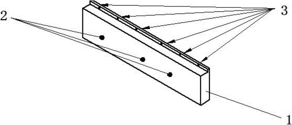
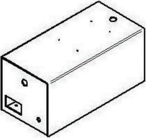
[0018] see figure 1 , figure 2 As shown, it illustrates an LED light source mechanism for UV side curing of a touch screen according to an embodiment of the present invention, including an irradiation head, and the irradiation head includes a first housing, which is a closed hollow structure provided with a fence, The outer wall of the housing is provided with six fixed points 3, the fixed points 3 are located on the same side wall, and are not equidistantly arranged; the light source 1 is an LED line light source, placed in the first housing, and passed through the The fence emits light to the outside; the heat dissipation unit 2 is located in the first housing and includes a plurality of CPU fans; the controller controls the light source 1 and the heat dissipation unit 2,...


PUM


Abstract

The invention discloses an LED (light-emitting diode) light source mechanism for curing a UV (ultraviolet) side of a touch screen. The LED light source mechanism comprises an irradiation head, a light source (1), a cooling unit (2), a controller, an MCU (micro-control unit) control module, an operation interface and a second shell, the irradiation head comprises a first shell which is of a sealed hollow structure with a barrier, the light source (1) is an LED line light source, is arranged in the first shell and externally emits light through the barrier, the cooling unit (2) is positioned in the first shell and comprises one or more than one fan, the controller controls the light source (1) and the cooling unit (2) and comprises a terminal, the terminal comprises an input end and an output end, the output end is connected with the first shell, the MCU control module is electrically connected with the input end and the output end, the operation interface is connected with the input end, the second shell is of a hollow structure, both the terminal and the MCU control module are positioned in the second shell, and the operation interface is positioned outside the second shell and connected with the second shell.

Description

technical field [0001] The invention relates to a light source, in particular to an LED light source mechanism. Background technique [0002] The touch screen production process involves side curing, and the light source is required to meet the following conditions: 1) High light uniformity; 2) Power greater than 1000mw / cm 2 ; 3) The temperature is lower than 50 degrees; 4) The curing depth is greater than 10mm; 5) The line light source, so LED UV line light source needs to be used as the light source mechanism for the UV side curing of the touch screen, and the development of the touch screen side curing device on the market is still in its infancy. At this stage, the use of LED line light sources for the touch screen side curing device still requires the design of a light source mechanism for the favorable side curing process, which includes light source structure design and necessary chip control. [0003] Based on the above, it is necessary to develop an LED light sourc...

Claims


Application Information

Patent Timeline
Patent Type & Authority Patents(China)
IPC IPC(8): F21S2/00F21V11/00F21V29/00G06F3/041F21Y101/02F21K9/23F21K9/237F21V29/61F21Y115/10
Inventor 林少渊
Owner KUNSHAN SAMON AUTOMATION TECH
Learn More