Clamping device for voltage-withstanding testing of capacitor core group

A technology of withstand voltage test and clamping device, applied in the direction of measuring device casing, etc., can solve the problems of reducing the reliability of capacitors, poor contact, damage to capacitor core groups, etc., saving charging and discharging time, enhancing contact strength, and improving labor efficiency Effect

Inactive Publication Date: 2014-01-01
ANHUI SAFE ELECTRONICS
View PDF8 Cites 8 Cited by
  • Summary
  • Abstract
  • Description
  • Claims
  • Application Information

AI Technical Summary

Problems solved by technology

The shortcomings of these two solutions are: the mandrel in the middle of the capacitor core group protrudes from the gold-sprayed surface by about 1 mm, and there is a certain error in the flatness of the end face of the capacitor body. If it is not good, high-voltage arcing will be generated, which will cause damage to the capacitor core group under test; while the fixed pressure push rod contact, the pressure is fixed, and it has a strong momentum at the moment of clamping the capacitor core group, which may easily lead to the soft base of the capacitor core group. Stress damage such as cracks and deformation on the gold end face
The deficiencies of the above two solutions increase the probability of early failure of the capacitor, reduce the reliability of the capacitor, and have a negative impact on the life of the capacitor

Method used


Image

  • Clamping device for voltage-withstanding testing of capacitor core group
  • Clamping device for voltage-withstanding testing of capacitor core group
  • Clamping device for voltage-withstanding testing of capacitor core group

Examples


Embodiment Construction

[0017] The content of the present invention will be described below in conjunction with specific embodiments.

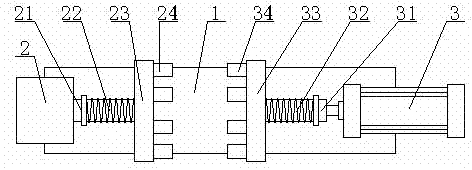
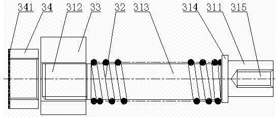
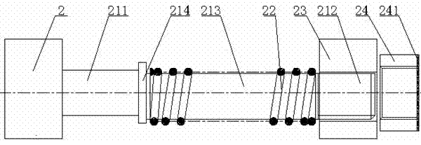
[0018] like Figure 1-5 As shown in FIG. 1 , it is a structural schematic diagram of the clamping device for withstand voltage testing of capacitor core packs according to the present invention. The clamping device for withstand voltage test of the capacitor core group according to the present invention includes: a base 1, a fixed part, and a movable part arranged opposite to the fixed part; it is characterized in that: the fixed part includes an end seat 2, a connecting rod 21. Spring one 22, installation seat one 23, fixed chute one 24, the end seat 2 is fixed on the base 1, the connecting rod one 21 connects the end seat 2 and the installation seat one 23 , the spring one 22 is arranged between the end seat 2 and the installation seat one 23, and the fixed chute one 24 is arranged on the said installation seat one 23 and there are a plurality of them. Generally, ...


PUM

PropertyMeasurementUnit
Heightaaaaaaaaaa
Elastic coefficientaaaaaaaaaa

Abstract

The invention discloses a clamping device for voltage-withstanding testing of a capacitor core group. The clamping device comprises a base, a fixing portion and a movable portion opposite to the fixing portion. The fixing portion comprises an end base, a first connecting rod, a first spring, a first installing base and multiple first fixing chutes, wherein the end base is fixedly arranged on the base, the first connecting rod is connected with the end base and the first installing base, and the multiple first fixing chutes are arranged on the first installing base. The movable portion comprises an air cylinder, a second connecting rod, a second spring, a second installing base and second fixing chutes, wherein the air cylinder is fixedly arranged on the base, the second connecting rod is connected with the air cylinder and the second installing base, and the second fixing chutes are arranged on the second installing base and are correspondingly opposite to the first fixing chutes. By adopting the mechanical combined design, the clamping device for the voltage-withstanding testing of the capacitor core group has the advantages of buffering pressure of the capacitor core group and being good in contact surface and can effectively avoid a phenomenon that a metal spraying layer of the end face of the metalized core group is damaged due to over-large impact force or the arc discharge damage is produced by poor contact surfaces caused by too low pressure.

Description

technical field [0001] The invention relates to a clamping device for withstand voltage testing of a capacitor core group, which belongs to the technical field of capacitor production and detection. Background technique [0002] At present, the widely used clamping devices for the withstand voltage test of the capacitor core group are mainly the copper plate type surface contact of the electrodes at both ends and the fixed pressure push rod type contact. The shortcomings of these two solutions are: the mandrel in the middle of the capacitor core group protrudes from the gold-sprayed surface by about 1 mm, and there is a certain error in the flatness of the end face of the capacitor body. If it is not good, high-voltage arcing will be generated, which will cause damage to the capacitor core group under test; while the fixed pressure push rod contact, the pressure is fixed, and it has a strong momentum at the moment of clamping the capacitor core group, which may easily lead t...

Claims


Application Information

Patent Timeline
IPC IPC(8): G01R1/04
Inventor 曹骏骅谢兴明
Owner ANHUI SAFE ELECTRONICS
Why Eureka
Try Eureka