

Venous valve repair prosthesis for treatment of chronic venous insufficiency
- Summary
- Abstract
- Description
- Claims
- Application Information
AI Technical Summary
Benefits of technology
Problems solved by technology
Method used
Image

Examples
Embodiment Construction
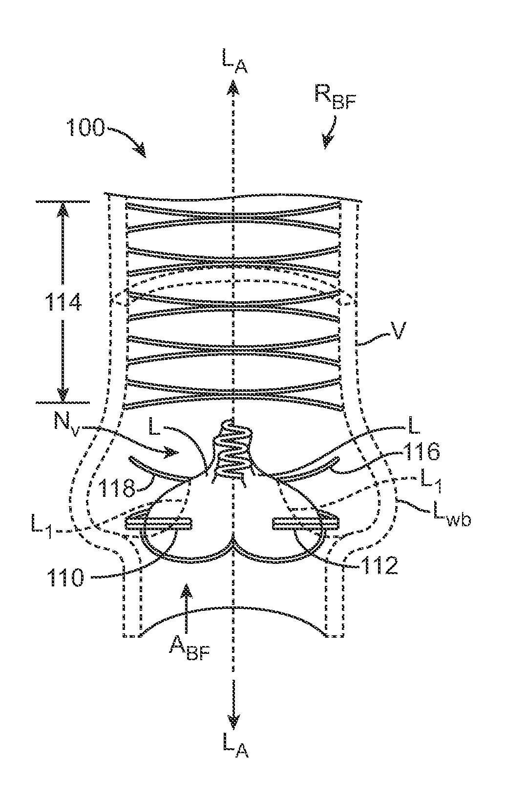
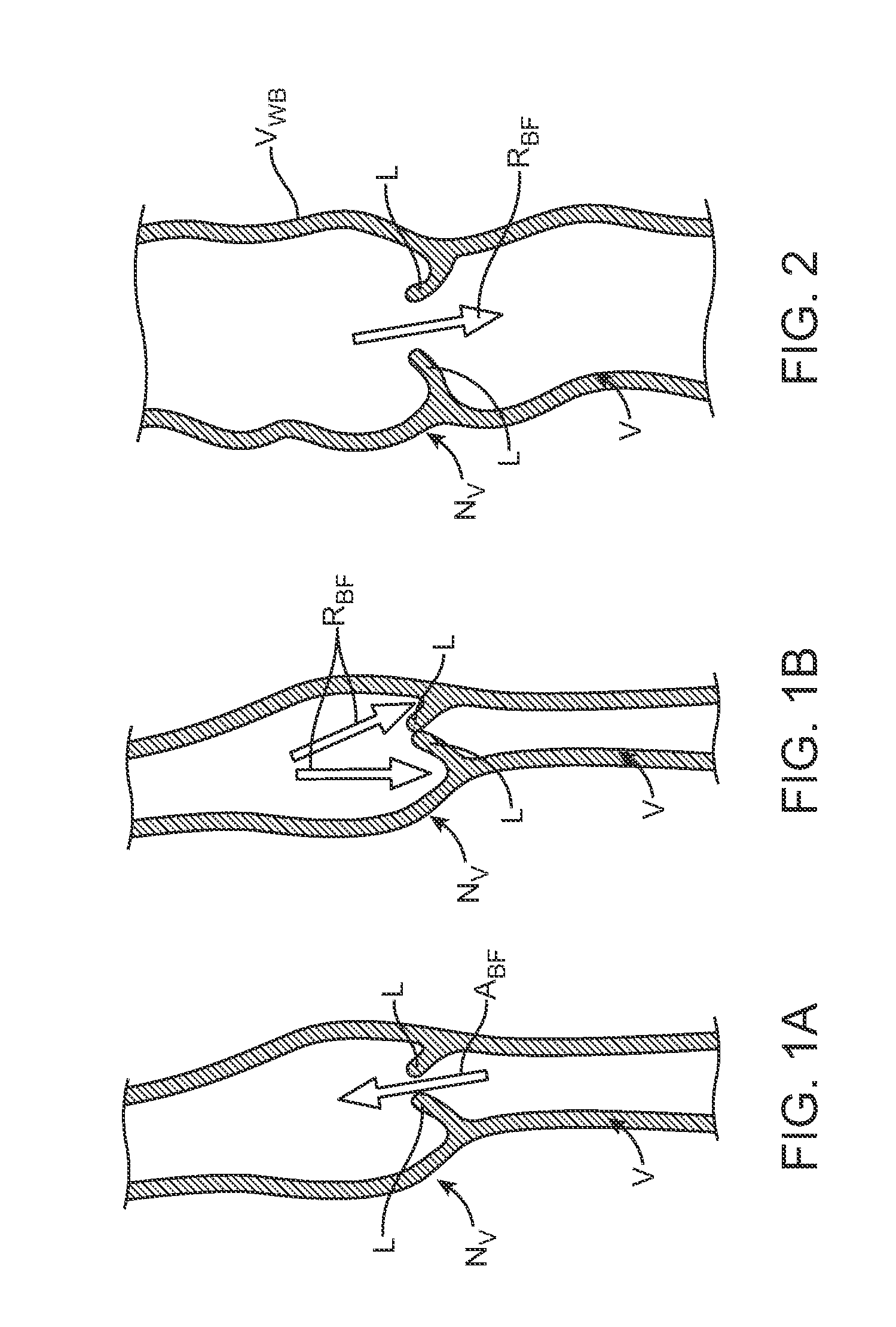
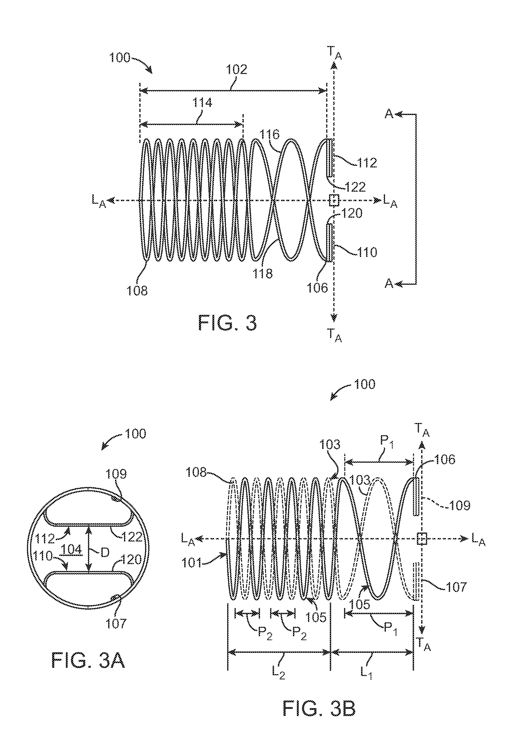
[0033]Specific embodiments of the present invention are described below with reference to the figures, wherein like reference numbers indicate identical or functionally similar elements. The terms “distal” and “proximal” are used in the following description with respect to a position or direction relative to the treating clinician. “Distal” or “distally” are a position distant from or in a direction away from the clinician. “Proximal” and “proximally” are a position near or in a direction toward the clinician. In addition, the term “self-expanding” is used in the following description with reference to the prostheses hereof and is intended to convey that the structures are shaped or formed from a material that can be provided with a mechanical memory to return the structure from a compressed or constricted delivery configuration to an expanded deployed configuration. Non-exhaustive exemplary materials that are suitable for forming self-expanding prosthesis in accordance with embodi...
PUM
 Abstract
Description
Claims
Application Information