Heat exchanger, method of manufacturing heat exchanger, liquid cooling system, light source device, projector, electronic device unit, and electronic equipment

A technology of heat exchanger and manufacturing method, applied in the cooling of instruments, parts of instruments, cooling/ventilation/heating renovation, etc., can solve problems such as electrolytic corrosion, reduced thermal conductivity, blocked flow paths, etc., and achieve good diffusion bonding , the effect of high efficiency

Inactive Publication Date: 2007-04-11
SEIKO EPSON CORP
View PDF1 Cites 14 Cited by
  • Summary
  • Abstract
  • Description
  • Claims
  • Application Information

AI Technical Summary

Problems solved by technology

[0007] However, in the above technique, there is a problem that the solder used for joining the thin plates flows into the flow path and clogs the flow path.
In addition, since the solder is interposed between the thin plates, there is a problem that the thermal conductivity in the stacking direction of the thin plates is greatly reduced.
Furthermore, since a metal different from the thin plate is sandwiched, the occurrence of electrolytic corrosion becomes a problem

Method used


Image

  • Heat exchanger, method of manufacturing heat exchanger, liquid cooling system, light source device, projector, electronic device unit, and electronic equipment
  • Heat exchanger, method of manufacturing heat exchanger, liquid cooling system, light source device, projector, electronic device unit, and electronic equipment
  • Heat exchanger, method of manufacturing heat exchanger, liquid cooling system, light source device, projector, electronic device unit, and electronic equipment

Examples


Embodiment Construction

[0040] Hereinafter, embodiments of the heat exchanger, the manufacturing method of the heat exchanger, the liquid cooling system, the light source device, the projector, the electronic device unit, and the electronic equipment of the present invention will be described with reference to the accompanying drawings.

[0041] 〔Heat exchanger〕

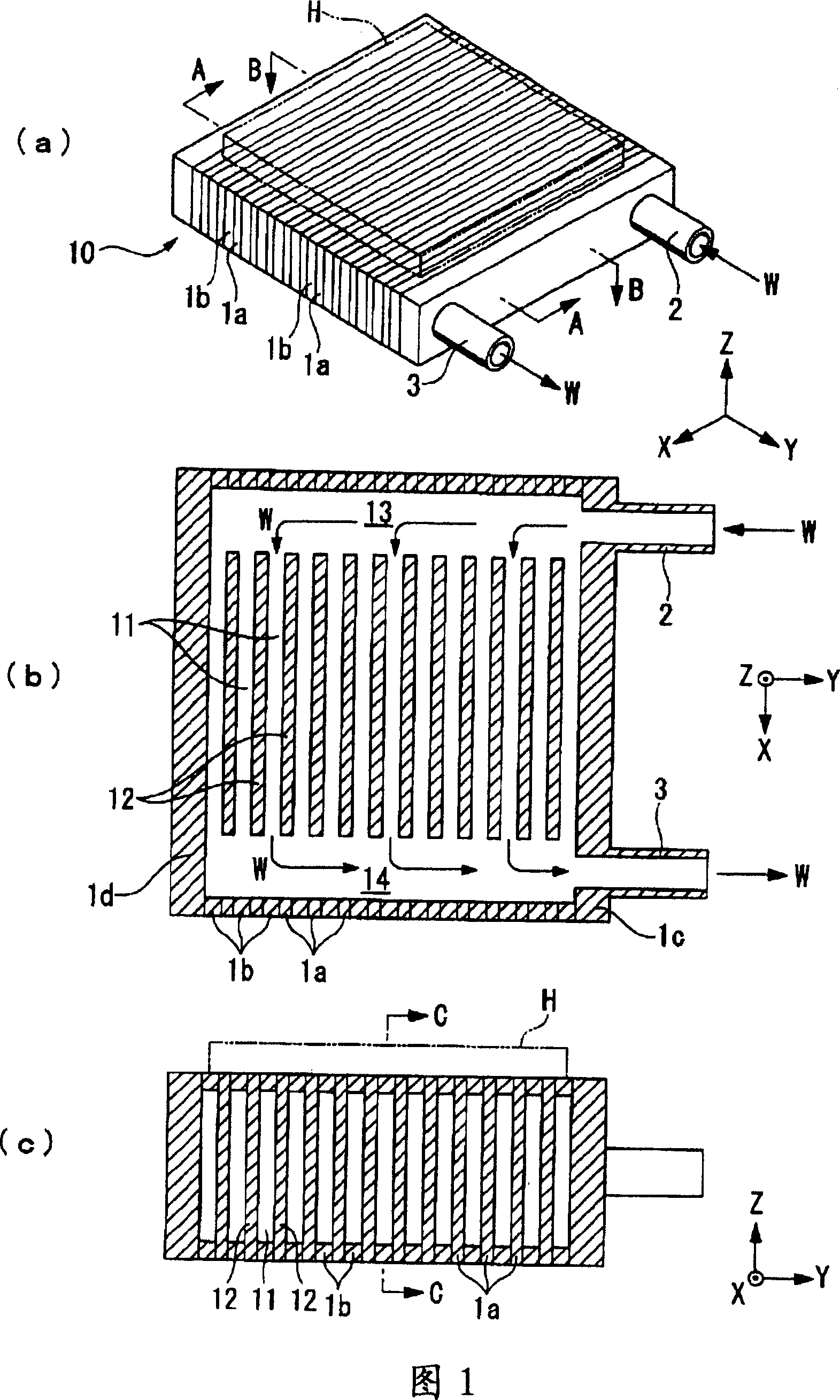
[0042] Fig. 1 is a diagram showing a schematic configuration of a heat exchanger, Fig. 1(a) is a perspective view, Fig. 1(b) is a longitudinal sectional view, and Fig. 1(c) is a transverse sectional view.

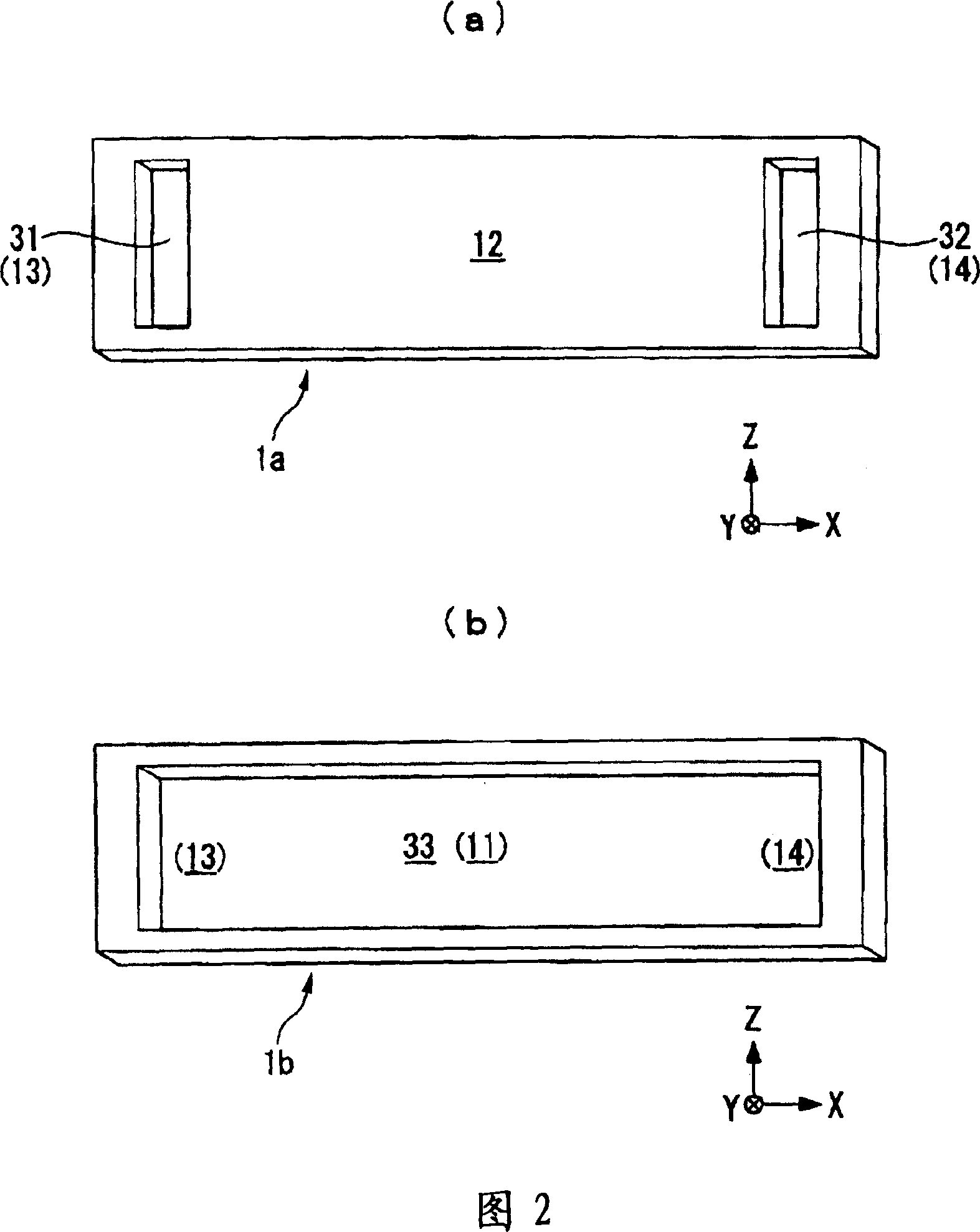
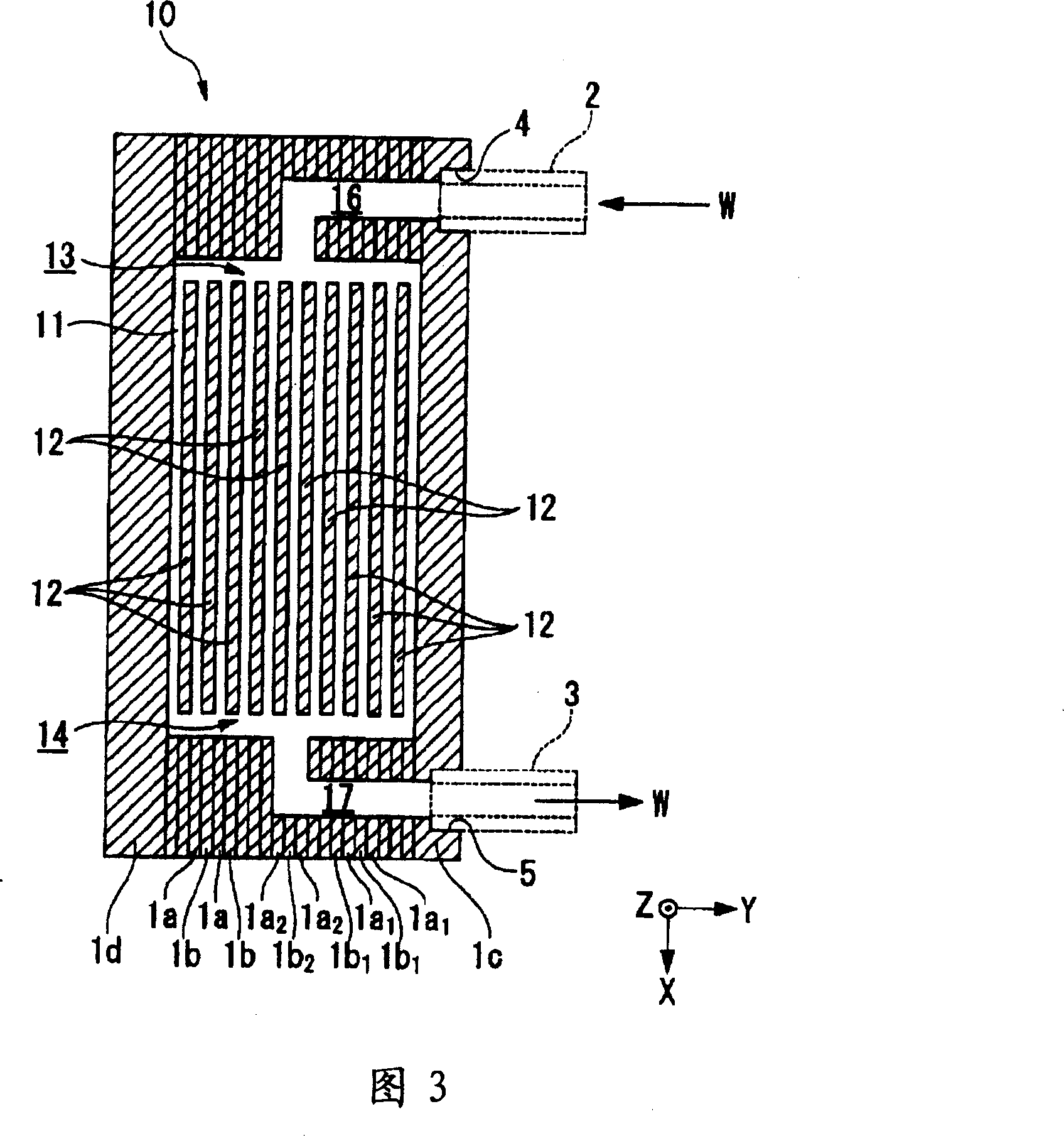
[0043] The heat exchanger 10 is a plate-shaped member formed by laminating a plurality of metal thin plates (laminated plates 1a, 1b, etc.) with high thermal conductivity such as copper or aluminum, and has a plurality of liquids such as water W inside it. The fine flow path 11.

[0044] As shown in FIG. 1( a ), on the side of the heat exchanger 10 , an introduction pipe 2 for introducing water W into the inside, and an outlet pipe 3 fo...


PUM


Abstract

The invention provides heat exchanger, method of manufacturing heat exchanger, liquid cooling system, light source device, projector, and electronic equipment.A method of manufacturing a heat exchanger having a plurality of fine flow channels includes forming a plurality of thin plate members into a predetermined shape, and laminating the plurality of thin plate members and bonding by diffusion bonding.

Description

technical field [0001] The present invention relates to a heat exchanger having a plurality of fine flow paths, a method of manufacturing the heat exchanger, and the like. Background technique [0002] In recent years, projectors have been pursued for miniaturization, high luminance, long life, low cost, and the like. For example, regarding miniaturization, the size of a liquid crystal panel (light modulation element) is reduced from 1.3 inches diagonally to about 0.5 inches, and the area ratio is smaller than 1 / 6. [0003] As a light source of a projector, miniaturization is achieved by using a light emitting diode (LED: Light Emitting Diode) or a laser diode (LD: Laser Diode) as a solid light source. LED light sources and the like are advantageous as light sources for projectors, including a small power supply, instant on / off, wide color reproducibility, and long life. In addition, since it does not contain harmful substances such as mercury, it is also good from the vie...

Claims


Application Information

Patent Timeline
Patent Type & Authority Applications(China)
IPC IPC(8): H05K7/20G12B15/02
Inventor 高城邦彦江川明
Owner SEIKO EPSON CORP
Why Eureka
Try Eureka