On-line touring system of power transmission line

A technology for transmission lines and subsystems, applied in the field of electric power, can solve the problems of limitation, reflect the operation status of the line, and low economic benefits, and achieve the effects of reducing resources, easy deployment, and reliable transmission.

Active Publication Date: 2014-01-01
HUAZHONG UNIV OF SCI & TECH
View PDF5 Cites 16 Cited by
  • Summary
  • Abstract
  • Description
  • Claims
  • Application Information

AI Technical Summary

Problems solved by technology

However, these status monitoring systems are limited by specific monitoring targets and monitoring methods are limited, so it is difficult to fully and accurately reflect the line operation status, cannot meet the requirements of line inspection, and it is difficult to expand functions; on the other hand, these monitoring systems are limited by GPRS or CDMA Information and communication technology has shortcomings such as small transmission data capacity, poor security and reliability, and cannot meet the real-time monitoring requirements of the state quantities required for line inspections.
Since these line status monitoring systems are out of touch with tasks such as daily inspections of transmission lines, the utilization rate is not high and the economic benefits are low

Method used


Image

  • On-line touring system of power transmission line
  • On-line touring system of power transmission line
  • On-line touring system of power transmission line

Examples


Embodiment Construction

[0023] In order to make the object, technical solution and advantages of the present invention clearer, the present invention will be further described in detail below in conjunction with the accompanying drawings and embodiments. It should be understood that the specific embodiments described here are only used to explain the present invention, not to limit the present invention. In addition, the technical features involved in the various embodiments of the present invention described below can be combined with each other as long as they do not constitute a conflict with each other.

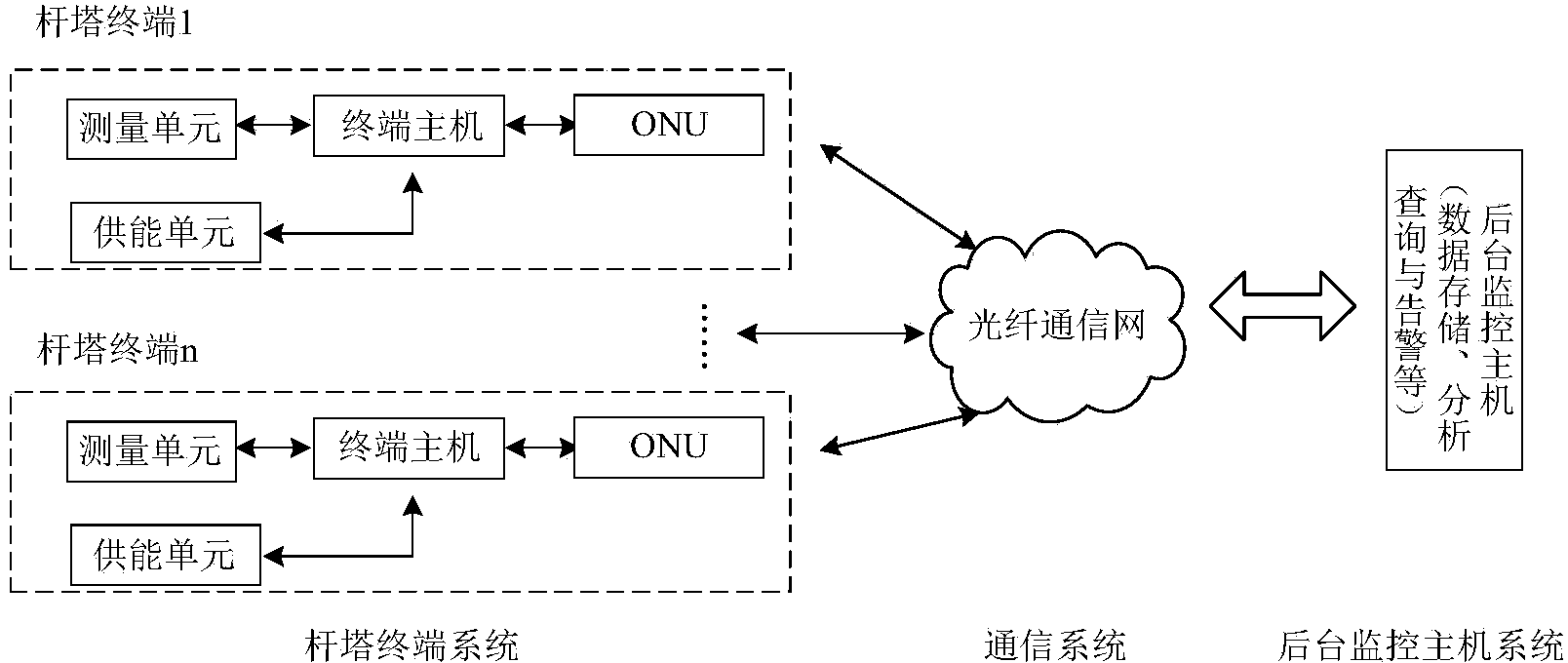
[0024] Such as figure 1 Shown is a schematic structural diagram of the transmission line on-line inspection system proposed by the present invention. The inspection system is mainly composed of an optical fiber communication subsystem, a background monitoring host subsystem, and a tower terminal subsystem configured tower by tower. The tower terminal subsystem includes a measurement unit, a ter...


PUM


Abstract

The invention discloses an on-line touring system of a power transmission line. The on-line system comprises an optical fiber communication subsystem, a backstage monitoring host subsystem and tower terminal subsystems which are arranged on towers one by one. Each tower terminal subsystem comprises a measuring unit, a terminal host, an energy supply unit and an optical network unit. The measuring units are used for collecting monitoring data in a power transmission circuit. The terminal hosts are used for finishing converging, pretreating and uploading of the monitoring data and receiving an order sent by the backstage monitoring host subsystem to control all the units. The energy supply units are used for providing energy for the measuring units and optical network unit devices through relay exits of the terminal hosts. The monitoring data collected by the tower terminal subsystems of all the towers are connected with the optical units through the optical network units, wherein the optical units are continuously led downwards from all the towers, and the monitoring data are connected into the optical fiber communication subsystem. The backstage monitoring host subsystem has the functions of storing the monitoring data, analyzing, inquiring, alarming and the like and is communicated with all the tower terminal subsystems through the optical fiber communication system.

Description

technical field [0001] The invention belongs to the field of electric power technology, and more specifically relates to an online inspection system for power transmission lines. Background technique [0002] With the development of the power system, the total length of high-voltage transmission lines in my country is increasing continuously, and the coverage is expanding. In order to ensure the safety of transmission lines and their equipment, the daily inspection of power system transmission lines is an important link. However, the manual inspection of high-voltage transmission lines has a large workload and high inspection cost, and the difficulty of manual inspection will be greatly increased in complex geographical environments and harsh weather conditions; although helicopter inspections can improve the efficiency of inspections, they have a significant impact on climate conditions and geographical environments. The requirements are strict and there are flight safety h...

Claims


Application Information

Patent Timeline
Patent Type & Authority Applications(China)
IPC IPC(8): G05B19/418H04B10/25
CPCY02P90/02
Inventor 尹项根唐金锐赵建青邱玩辉姚瑶李振宇刘洪洁
Owner HUAZHONG UNIV OF SCI & TECH
Why Eureka
Try Eureka