
Field operation optimization method for SCR (selective catalytic reduction) denitration system

A technology of on-site operation and optimization method, which is applied in special data processing applications, instruments, electrical digital data processing, etc., and can solve problems such as low efficiency and high cost

Inactive Publication Date: 2014-01-01
ELECTRIC POWER RES INST OF GUANGDONG POWER GRID
View PDF1 Cites 19 Cited by
  • Summary
  • Abstract
  • Description
  • Claims
  • Application Information

AI Technical Summary

Problems solved by technology

[0035] Based on this, it is necessary to provide an on-site operation optimization method for the SCR denitrification system to address the above-mentioned problems of high cost and low efficiency, which can reduce the on-site operation optimization cost of the SCR denitrification system and improve the on-site optimization efficiency

Method used


Image

  • Field operation optimization method for SCR (selective catalytic reduction) denitration system
  • Field operation optimization method for SCR (selective catalytic reduction) denitration system
  • Field operation optimization method for SCR (selective catalytic reduction) denitration system

Examples


Embodiment Construction

[0052] The specific implementation of the on-site operation optimization method of the SCR denitrification system of the present invention will be described in detail below in conjunction with the accompanying drawings.

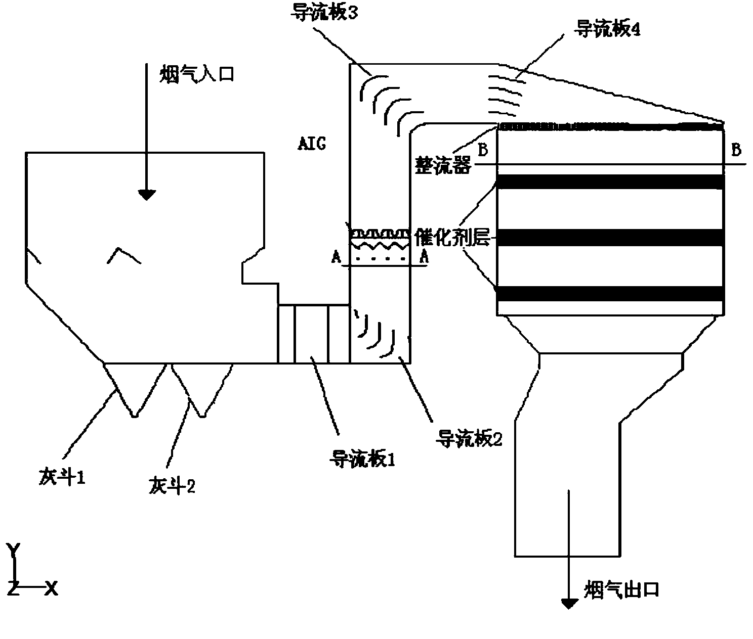
[0053] refer to figure 1 as shown, figure 1 It is a partial structural diagram of the SCR denitrification system. The figure shows the part from the flue gas inlet to the flue gas outlet, including the ash hopper, the flue and the reactor. Among them, the reactor is equipped with a rectifier and a catalyst layer. Its working principle is: By adding ammonia to the flue gas at a certain temperature, under the action of a catalyst, it can selectively reduce and react with NO to form N2 and H2O.

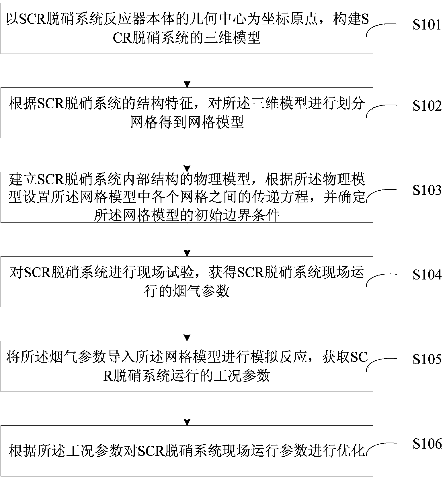
[0054] see figure 2 as shown, figure 2 It is a flow chart of the on-site operation optimization method of the SCR denitrification system of an embodiment, which mainly includes the following steps:

[0055] Step S101, taking the geometric center of the reactor bod...


PUM


Abstract

A field operation optimization method for an SCR (selective catalytic reduction) denitration system includes the steps of using a geometric center of an SCR denitration system reactor body as an origin of coordinates to establish a three-dimensional model of the SCR denitration system; meshing the three-dimensional model according to structural features of the SCR denitration system to obtain a mesh model; establishing a physical model for internal structure of the SCR denitration system, setting transfer equations for meshes in the mesh grid according to the physical model, and determining initial boundary conditions of the mesh grid; subjecting the SCR denitration system to field test so as to obtain smoke parameters of field operation of the SCR denitration system; introducing smoke parameters into the mesh model to allow for simulation reaction to acquire operational condition parameters of the SCR denitration system; subjecting the SCR denitration system to field operation parameter optimization according to the condition parameters. The method has the advantages that optimization cost can be reduced, optimization efficiency can be improved, and more accurate condition parameters can be obtained by changing meshing and parameter settings so that optimization accuracy can be improved.

Description

technical field [0001] The invention relates to the technical field of electric power engineering, in particular to an on-site operation optimization method of an SCR denitrification system. Background technique [0002] Air pollution is one of the prominent environmental problems facing the world. According to the different states of pollutants, it can be roughly divided into two categories: aerosol state pollutants and gaseous state pollutants. Among them, gaseous state pollutants include SO 2 The main sulfur compounds, NO x Mainly nitrogen-containing compounds, hydrocarbons and halogen compounds. Nitrogenous compounds are mainly NO, NO 2 , N 2 O, N 2 o 3 , N 2 o 4 , N 2 o 5 , the nitrogen oxides produced during the combustion process are mainly NO and NO 2 . [0003] With atmospheric NO x As the concentration increases, a series of urban and regional environmental problems become more prominent, which poses a huge threat to human health and the ecological envi...

Claims


Application Information

Patent Timeline
IPC IPC(8): G06F17/50G06F19/00
Inventor 李德波
Owner ELECTRIC POWER RES INST OF GUANGDONG POWER GRID
Learn More