
Anti-flooding control method for fuel cell

A fuel cell and control method technology, applied in fuel cells, fuel cell additives, circuits, etc., can solve a large number of problems, poor engineering applicability, no early warning and self-healing, etc.

Active Publication Date: 2014-01-01
TSINGHUA UNIV
View PDF2 Cites 11 Cited by
  • Summary
  • Abstract
  • Description
  • Claims
  • Application Information

AI Technical Summary

Problems solved by technology

[0003] Existing diagnostic methods for fuel cell water flooding or water shortage are mainly divided into three categories: by establishing fuel cell water management models, more suitable suggestions for fuel cell operating conditions can be given, but the diagnostic accuracy is not high and engineering Poor applicability; using engineering fault diagnosis methods such as neural networks or fault trees to diagnose flooding or water shortage requires a large amount of sample data and lacks sufficient interpretation; through air (cathode gas) pressure drop or fuel cell ohmic impedance The two methods can more accurately diagnose the flooding or water shortage of fuel cells, but lack of scientific and effective benchmark values, so the diagnosis can only be made when the flooding or water shortage has already occurred and is quite serious, and cannot be carried out from the trend Timely early warning and self-healing
[0004] For fuel cells that operate continuously, it is necessary to monitor the water state inside the battery in real time, to give early warning to the trend of water flooding or water shortage in the battery, and to take timely measures to self-heal. At present, there is a lack of a convenient and effective fuel cell Online technical method for early warning and self-healing of flooding and water shortage

Method used


Image

  • Anti-flooding control method for fuel cell
  • Anti-flooding control method for fuel cell
  • Anti-flooding control method for fuel cell

Examples


Embodiment Construction

[0024] The present invention will be further described in detail below in conjunction with the accompanying drawings and specific embodiments.

[0025] The main body of the present invention is the fuel cell anti-flooding control module, which can be applied to but not limited to the fuel cell measurement and control platform. The fuel cell measurement and control platform usually includes a fuel supply system, a fuel humidification system, a cooling water circulation system, a fuel cell system, and an electronic load system. And related necessary sensors, actuators and pipelines, etc., to make the fuel cell operate under the specified working conditions. The necessary sensor signals are converted into voltage signals and then input to the fuel cell anti-flooding control module, including the current value I of the fuel cell, the reaction temperature value T of the fuel cell, and the flow value of hydrogen (and calculate the excess coefficient value converted into hydrogen ) ...


PUM


Abstract

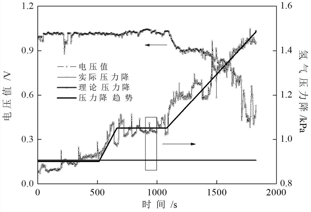
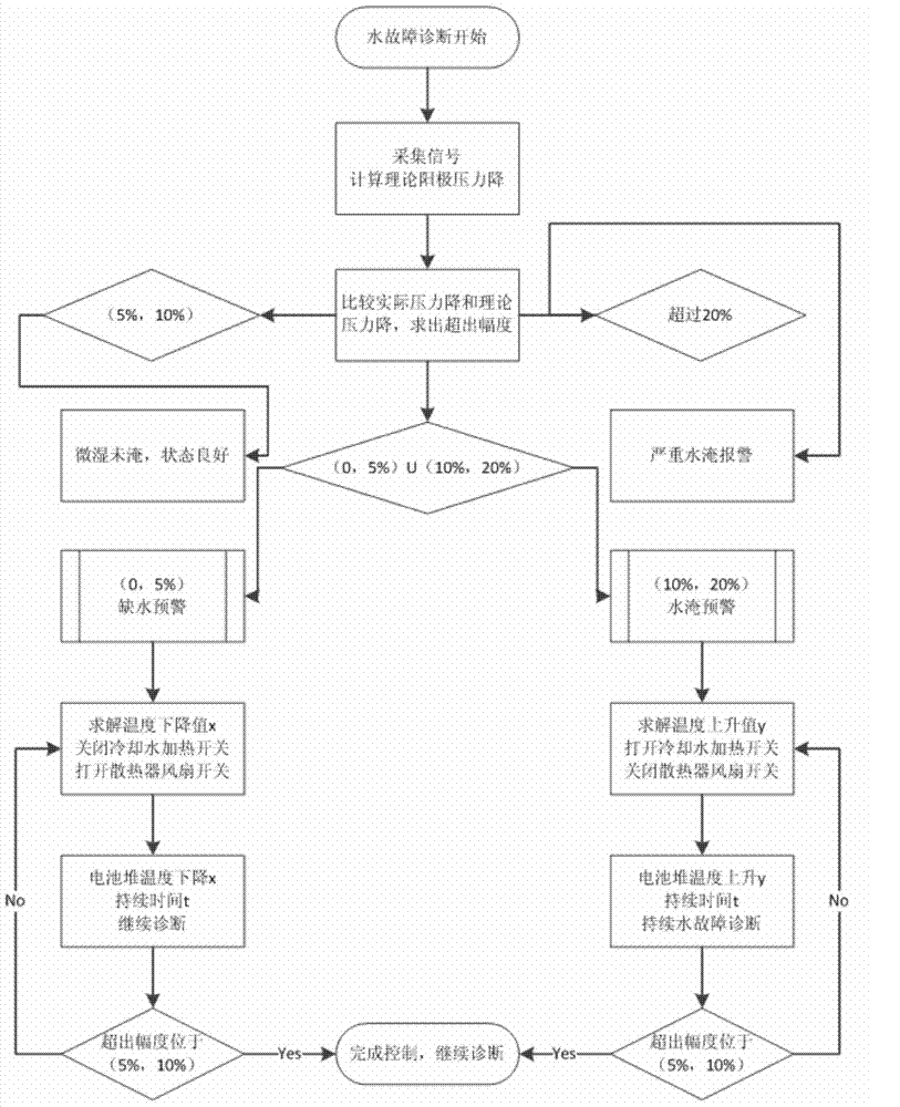
An anti-flooding control method for a fuel cell includes the following steps: a theoretical calculating value of hydrogen pressure drop of a fuel cell to be controlled in normal operation is obtained through flow field parameter calculation or experimental test; an upper control limit of the hydrogen pressure drop of the fuel cell to be controlled is used for preventing the fuel cell from being flooded, and is obtained according to flooding experiments or runner parameters, and a slightly moistened and non-flooded interval of the fuel cell to be controlled is confirmed; the water condition of the fuel cell to be controlled is evaluated by detecting the hydrogen pressure drop, and the anti-flooding control is realized through adjusting the reaction temperature and stabilization time. According to the method, the theoretical calculating value of the hydrogen pressure drop of the fuel cell, as well as the change features of the flooding process of the fuel cell and the control interval of the hydrogen pressure drop are given, the method is suitable for a measurement and control platform system for fuel cells or various conditions of practical application of fuel cells, and has the advantages of being simple, quick, scientific, accurate, timely and the like.

Description

technical field [0001] The invention relates to the technical field of fuel cell water management and fault diagnosis, in particular to a fuel cell anti-flooding control method. Background technique [0002] The topic of water management is the key and difficult point in the operation of fuel cells, which is directly related to the performance indicators and even the life of fuel cells. Poor water management is usually divided into two situations: water flooding and water shortage. Flooding will hinder the flow of fuel gas, cause reaction lack of gas and cause other side reactions, accelerate the corrosion of carbon in the catalytic layer, and cause local temperature hot spots ; Lack of water will lead to the drying of the proton exchange membrane, significantly reduce the proton conductivity, and even cause the rupture and damage of the proton exchange membrane. Therefore, it is very necessary to diagnose the flooding and water shortage of the fuel cell. [0003] Existing...

Claims


Application Information

Patent Timeline
IPC IPC(8): H01M8/04H01M8/04119H01M8/0438H01M8/04664H01M8/04992
CPCY02E60/50H01M8/04432
Inventor 裴普成宋满存
Owner TSINGHUA UNIV
Learn More