An array antenna

An array antenna and printed circuit technology, applied in the directions of antennas, antenna arrays, antenna supports/installation devices, etc., can solve the problems of large loss of radio frequency cables, poor production consistency, high gain, etc., and achieve high gain and guaranteed production. Consistency, cost reduction effect

Inactive Publication Date: 2015-11-11
FOSHAN LANBOWANJIN TECH CO LTD
View PDF15 Cites 1 Cited by
  • Summary
  • Abstract
  • Description
  • Claims
  • Application Information

AI Technical Summary

Problems solved by technology

For example, US6195063B1, this type of antenna generally uses a metal vibrator as the radiation unit, and uses a radio frequency cable as the main component of the feed network. Its disadvantages are that there are many solder joints and poor production consistency. Higher requirements for the antenna production process; second, when some special requirements such as high gain requirements, the loss of the radio frequency cable is too large, which cannot meet the requirements
[0004] Secondly, in the current existing technologies, some technologies use patch antennas as the radiation unit, and the feed network can use high-frequency microstrip circuit boards, such as US8378915B2. The integrated processing of the two can solve the problem of production consistency, but High-frequency microstrip circuit boards are expensive and have large losses
[0005] Again, among the existing technologies at present, some technologies adopt the form of air microstrip to replace the high-frequency microstrip circuit board, such as US6034649, the form of air microstrip is used to replace the high-frequency microstrip circuit board, although this technology can make the feed network The loss is reduced and the gain of the antenna is improved, but the air microstrip line is difficult to fix, and the production consistency is poor, so it is not suitable for use in base station antennas with higher frequencies such as 5GH and above
[0006] That is, the existing array antennas cannot meet the requirements of low cost, high gain, and production consistency at the same time

Method used


Image

  • An array antenna
  • An array antenna
  • An array antenna

Examples


Embodiment Construction

[0042] In order to make the object, technical solution and advantages of the present invention clearer, the present invention will be further described in detail below in conjunction with the accompanying drawings. It is only stated here that the words for directions such as up, down, left, right, front, back, inside, and outside that appear or will appear in the text of the present invention are only based on the accompanying drawings of the present invention, and are not specific to the present invention. limited.

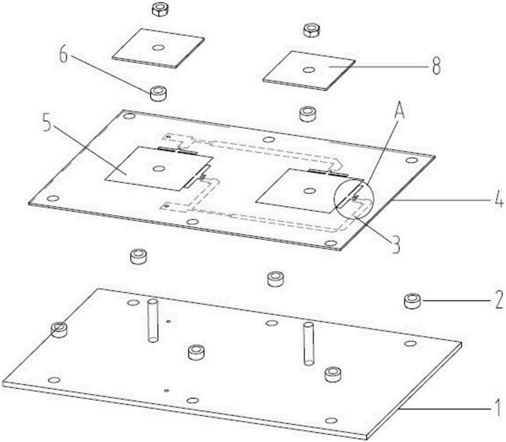
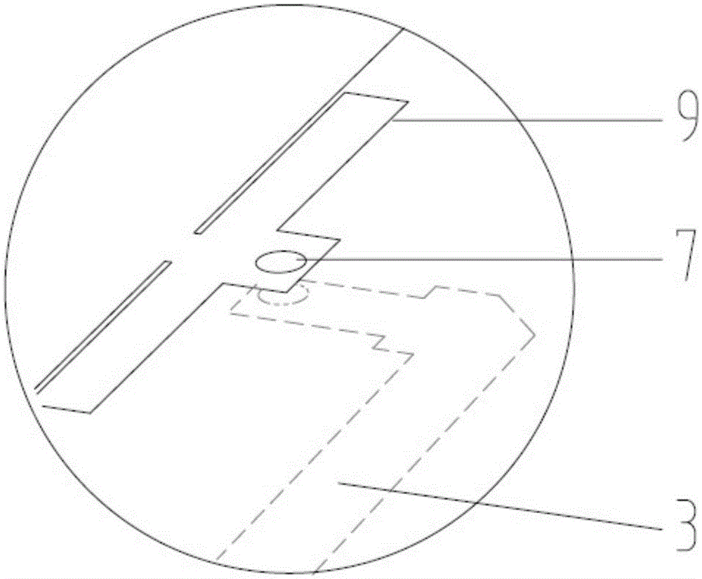
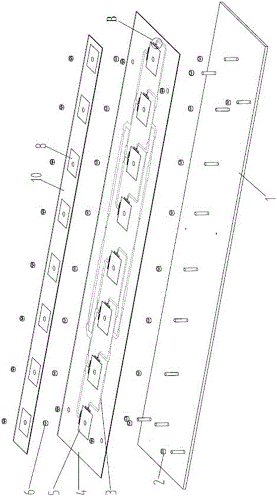
[0043] The present invention provides an array antenna, which includes a bottom plate, a printed circuit and a printed circuit board substrate, the printed circuit board substrate is placed on the bottom plate through supporting columns, and there is a gap between the printed circuit board substrate and the bottom plate Air layer; the printed circuit board is provided with the printed circuit on the lower surface of the printed circuit board substrate, and the pr...


PUM


Abstract

The invention discloses an array antenna which comprises a bottom plate, a printed circuit and a printed circuit base board. The printed circuit base board is arranged on the bottom plate through a supporting column, an air layer is formed between the printed circuit base board of the bottom plate, the printed circuit is arranged on the lower surface of the printed circuit base board, the printed circuit is arranged above the air layer and under the printed circuit base board, a printing radiating unit is positioned on the upper surface of the printed circuit base board, and the printing radiating unit is electrically connected with the printed circuit. The array antenna is low in cost, high in gain and good in production conformity.

Description

technical field [0001] The invention relates to a transceiver antenna device for a base station in mobile communication, in particular to an array antenna suitable for a 3G / 4G high-gain mobile communication base station. Background technique [0002] As the throat of the wireless communication system, the antenna is a system component that radiates and receives electromagnetic waves. The performance of the antenna plays a very important role in the overall performance of the mobile communication system. A pair of high-performance antennas can relax the requirements of the system and improve the performance of the entire system. Today, the continuous upgrading of mobile communication systems provides new requirements for antennas. Miniaturization, low profile, wide frequency band, low cost, ruggedness and ease of system integration have become the main factors that modern antenna designers need to consider. Especially with the advent and marketization of 3G / 4G systems, the d...

Claims


Application Information

Patent Timeline
Patent Type & Authority Patents(China)
IPC IPC(8): H01Q1/22H01Q13/08H01Q21/00
Inventor 金西荣
Owner FOSHAN LANBOWANJIN TECH CO LTD
Why Eureka
Try Eureka