Novel motor shell welding equipment

A technology for motor housings and welding equipment, applied in welding equipment, welding equipment, laser welding equipment and other directions, can solve the problems of reducing the accuracy of welding, the products are prone to scratches, and the speed of processing is affected, so as to improve the Accuracy, avoid sparks flying upwards, easy to intercept the effect

Inactive Publication Date: 2021-10-08
彭鹏飞
View PDF1 Cites 1 Cited by
  • Summary
  • Abstract
  • Description
  • Claims
  • Application Information

AI Technical Summary

Problems solved by technology

[0006] Aiming at the deficiencies of the prior art, the present invention provides a new type of motor shell welding equipment, which solves the problem that the welding position of the device is prone to shift during welding, reduces the accuracy of welding, and reduces the speed of installation. Slow, easy to affect the processing speed, and the processed products are prone to scratches

Method used


Image

  • Novel motor shell welding equipment
  • Novel motor shell welding equipment
  • Novel motor shell welding equipment

Examples


Embodiment 1

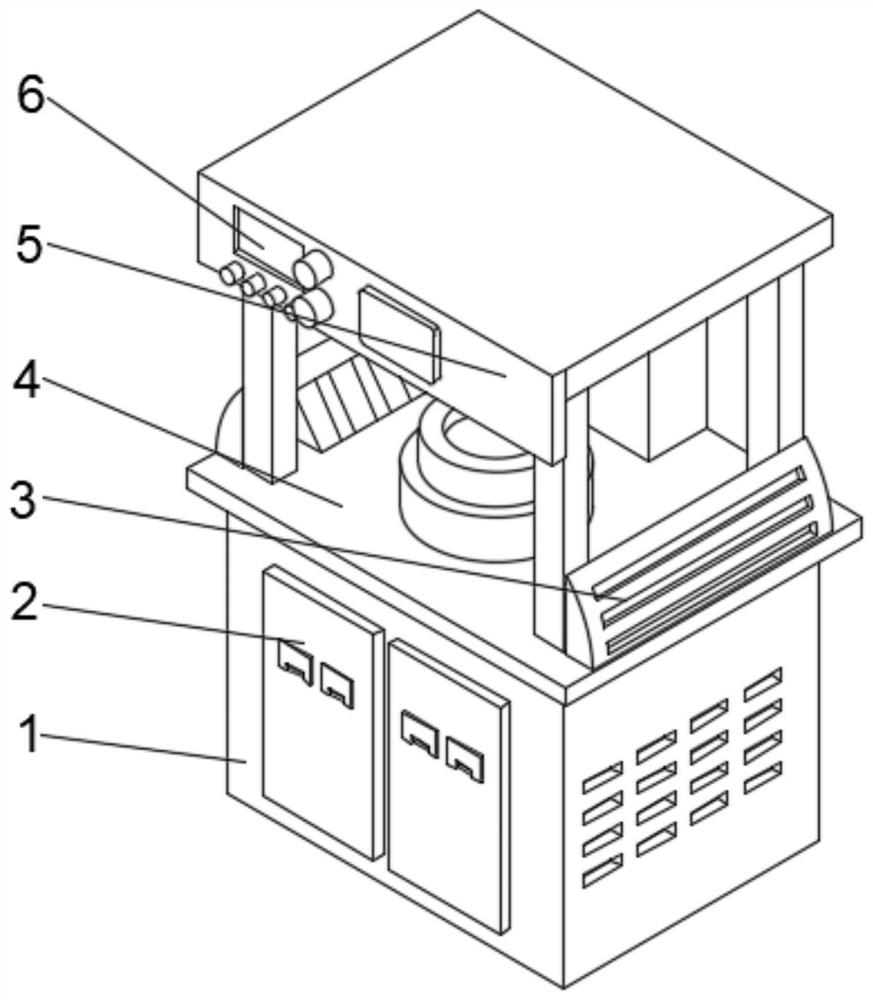
[0033] see Figure 1-2 , the present invention provides a technical solution: a new type of motor shell welding equipment, including a welding main body 1, the front and bottom sides of the welding main body 1 are provided with box doors 2, and the top of the welding main body 1 is fixedly connected with a welding device 4 The two sides of the top of the welding device 4 are fixedly connected with a blocking frame 3, the bottom of the blocking frame 3 runs through the welding device 4 and extends to the inside of the welding device 4, the top of the blocking frame 3 is fixedly connected with a cover plate 5, and the front side of the cover plate 5 The right side is fixedly connected with control panel 6.

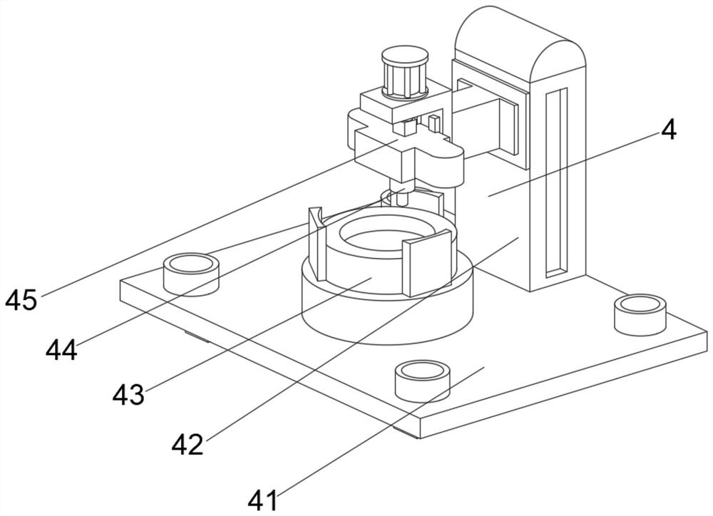
[0034] Wherein, the welding device 4 includes a welding platform 41, the top middle position of the welding platform 41 is fixedly connected with a fastening mechanism 43, the surface top middle position of the welding platform 41 is fixedly connected with a column 42, and t...

Embodiment 2

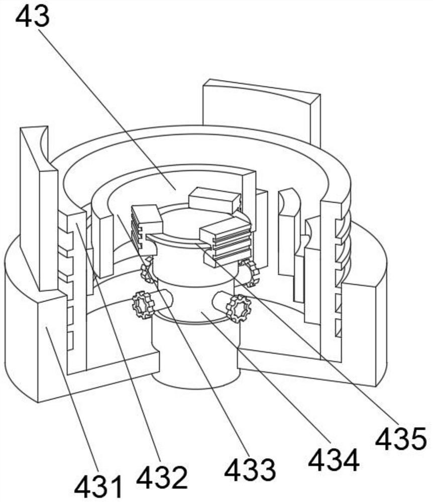
[0037] see Figure 1-4, on the basis of Embodiment 1, the present invention provides a technical solution: Component 1 of the fastening mechanism 43 includes a clamping seat 431, and a rotating column 434 is provided at the middle position of the inner cavity bottom of the clamping seat 431, and the rotating column 434 The top is fixedly connected with a fixer 435, and the bottom of the inner cavity of the clamping seat 431 is located on both sides of the rotating column 434 and is fixedly connected with a lifting positioning plate 432, and a contact body 433 is arranged in the middle of the inner wall of both sides of the lifting positioning plate 432.

[0038] Wherein, the first component of the protective mechanism 45 includes a fixed plate 451, the left outer wall of the fixed plate 451 is fixedly connected with a crossbeam 452, and the position of the crossbeam 452 away from the fixed plate 451 is fixedly connected with a force frame 453, and the top middle position of the...

Embodiment 3

[0041] see Figure 1-6 , on the basis of Embodiment 1 and Embodiment 2, the present invention provides a technical solution: component 2 of the fastening mechanism 43 includes a bottom plate d1, and the middle position of the top of the base plate can be fixedly connected with a fastener d5, The middle position of the outer walls on both sides of the fastener d5 is fixedly connected with a support plate d4, and the top of the bottom plate d1 is fixedly connected with an auxiliary positioning frame d2 on both sides of the fastener d5, and the auxiliary positioning frame d2 is close to one side of the fastener d5. The side top is provided with a positioning aid d3.

[0042] Wherein, the second component of the protection mechanism 45 includes a sliding block t1, the outer walls of both sides of the sliding block t1 are provided with a protective frame t2, and the middle position of the inner cavity bottom of the protective frame t2 is provided with a cooler t3, and the bottom of...


PUM


Abstract

The invention discloses novel motor shell welding equipment. The equipment comprises a welding main body, wherein box doors are arranged at the two sides of the bottom of the front face of the welding main body; a welding device is fixedly connected to the top of the welding main body; blocking frames are fixedly connected to the two sides of the top of the welding device; a cover plate is fixedly connected to the tops of the blocking frames; and the right side of the front surface of the cover plate is fixedly connected with a control panel. The invention relates to the technical field of motor shells. According to the novel motor shell welding equipment, a laser welding device has good stability during welding, the situation of blocking is not prone to occurring in the moving process, so that the accuracy during welding is improved, and the situation of repeated welding or welding missing is avoided; and clamping blocks are arranged on the welding platform, the connecting position of the device can be fixed, sparks generated during welding are conveniently intercepted, workers are effectively prevented from being injured, the cover plate can prevent the sparks from splashing upwards, and the use safety of the device is further improved.

Description

technical field [0001] The invention relates to the technical field of motor casings, in particular to a new type of welding equipment for motor casings. Background technique [0002] The main function of the motor is to generate driving torque. As a power source for electrical appliances or various machines, the main function of the generator is to convert mechanical energy into electrical energy. The motor needs a motor casing for protection, and the motor casing is made of light alloy through manual Welding equipment is welded. [0003] According to the light alloy motor shell welding equipment disclosed in Chinese Patent No. CN110238551B, the sheet material is fed from the feeding port, and the sheet material moves along the inner wall of the forming cylinder under the drive of the driving roller and produces plastic deformation until it is rounded. Welding is performed again to achieve the effect of simplifying the processing procedure and reducing the cumulative error...

Claims


Application Information

Patent Timeline
Patent Type & Authority Applications(China)
IPC IPC(8): B23K26/21B23K26/70B23K26/142B23K37/04H02K15/14
CPCB23K26/21B23K26/702B23K26/703B23K37/04B23K26/142H02K15/14
Inventor 彭鹏飞
Owner 彭鹏飞
Why Eureka
Try Eureka