High-gain smoothing antenna

A filter antenna and high-gain technology, applied in the field of high-gain filter antennas, can solve the problems of inconvenient installation and carrying, and achieve the effect of simple feeding

Inactive Publication Date: 2014-01-01
COMBA TELECOM TECH (GUANGZHOU) CO LTD
View PDF5 Cites 6 Cited by
  • Summary
  • Abstract
  • Description
  • Claims
  • Application Information

AI Technical Summary

Problems solved by technology

Although the reflector antenna saves the complicated feed network, the feed placed at the focal point in front of the reflector makes the overall profile height of the antenna several times the working wavelength. Therefore, its three-dimensional structure makes installation and portability inconvenient

Method used


Image

  • High-gain smoothing antenna
  • High-gain smoothing antenna
  • High-gain smoothing antenna

Examples


Embodiment Construction

[0034] The present invention will be described in detail below in conjunction with the accompanying drawings and embodiments.

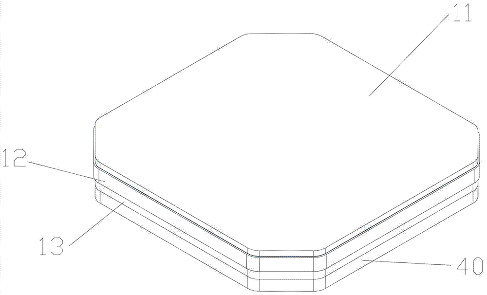
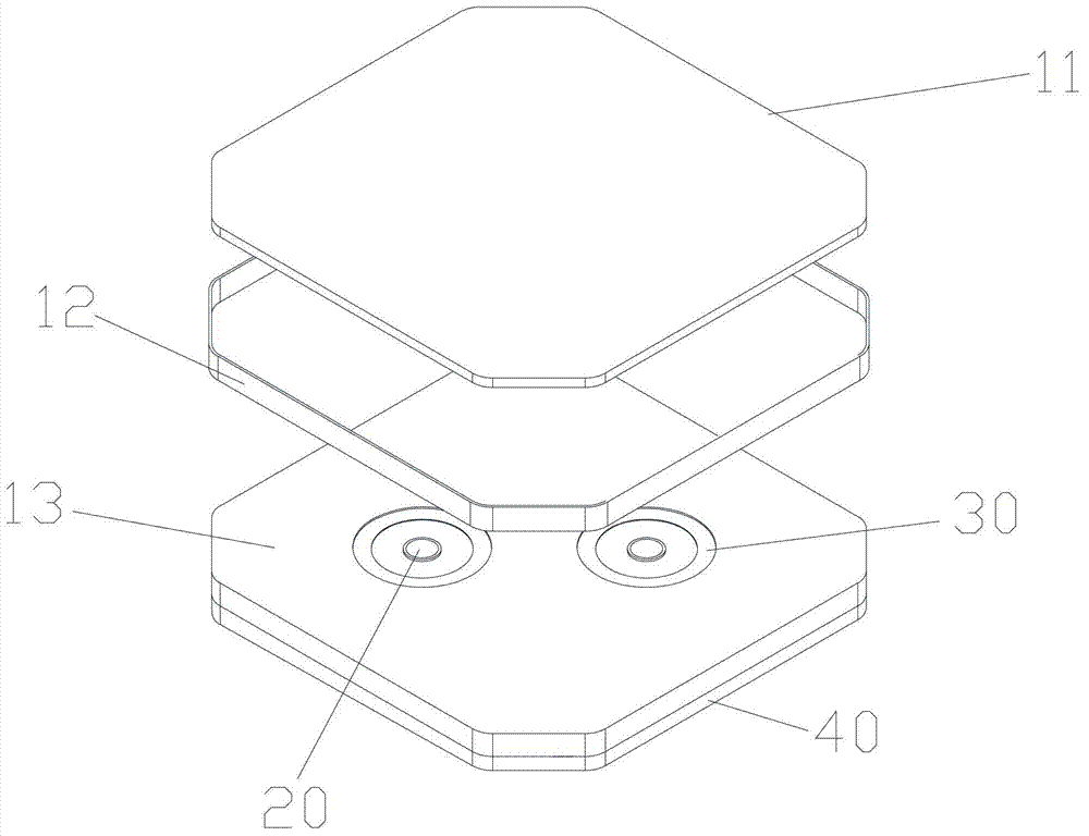
[0035] In a preferred embodiment of the present invention, the high-gain filter antenna includes a resonant cavity and at least one feed source placed in the resonant cavity.

[0036] Wherein, the resonant cavity has a metal reflection plate for fixing the feed, a metal frame erected on the reflection plate, and a metal grid for covering the metal frame and forming a through hole for the feed signal to radiate outward.

[0037] In this preferred embodiment, the metal grid can have various shapes, such as:

[0038] A. The metal grid is a metal strip arranged at intervals to leave a number of through holes, and the two ends of the metal strip are connected with the metal enclosure. Wherein, the metal strips are vertically arranged, that is, each metal strip is vertically long, and the metal strips are arranged parallel to each other.

[0039] B. Some ...


PUM


Abstract

The invention discloses a high-gain smoothing antenna which comprises a resonant cavity and at least one feed source placed in the resonant cavity. The resonant cavity is provided with a metal reflection plate, a metal enclosing frame and a metal grid. The metal reflection plate is used for fixing the feed source, the metal enclosing frame is erected on the reflection plate and the metal grid is used for covering the metal enclosing frame and provided with through holes used for outward irradiation of feed source signals. The feed source is a circular waveguide, or a square waveguide, or a rectangular waveguide or a loudspeaker. Through the mode, the high-gain smoothing antenna can integrate smoothing and gaining and meanwhile has the advantages of being easy to feed, high in gaining and the like.

Description

technical field [0001] The invention relates to the field of antennas, in particular to a high-gain filter antenna. Background technique [0002] With the development of communication system integration, more and more attention has been paid to the integration of multifunctional modules and the multifunctionalization of modules, such as: the baseband part, the signal processing part and the active radio frequency part can be chipped. However, it is difficult to achieve chip integration for passive components such as filters and antennas required by the RF front-end, because passive components require sufficient electrical dimensions to achieve the required electrical performance. In the prior art, passive devices are usually integrated into a chip or a package structure of a system. [0003] At present, in passive systems, there are two integration schemes for filter antennas that integrate filter characteristics and radiation characteristics, one is the traditional scheme ...

Claims


Application Information

Patent Timeline
IPC IPC(8): H01Q13/18H01Q19/10
Inventor 姜汝丹李岳峰王岩谢巍吴知航
Owner COMBA TELECOM TECH (GUANGZHOU) CO LTD
Why Eureka
Try Eureka