Flat plate magnet collecting type magnetic circuit structure for permanent magnet synchronous transmission device

A technology of transmission and permanent magnet synchronization, which is applied in the direction of synchronous clutch/brake, etc., can solve the problems of increasing the overall size of the transmission, increasing the number of permanent magnets, and reducing the magnetic torque, so as to increase the transmission torque and reduce the magnetic torque. Dimensions, the effect of reducing magnetic flux leakage

Active Publication Date: 2014-01-01
LIAOYANG TAIKE LEINUO SCI & TECH
View PDF5 Cites 5 Cited by
  • Summary
  • Abstract
  • Description
  • Claims
  • Application Information

AI Technical Summary

Problems solved by technology

However, due to the close arrangement of permanent magnets and the staggered arrangement of magnetic pole directions, it is easy to generate a loop of magnetic force lines between adjacent opposite magnetic poles, resulting in partial magnetic flux failure, resulting in local magnetic flux leakage between magnetic poles, thereby reducing to a certain extent The resulting magnetic torque
In order to meet the requirements of its transmission torque, it is necessary to increase the overall size of the transmission device and increase the number of permanent magnets, which will increase the cost of the product.

Method used


Image

  • Flat plate magnet collecting type magnetic circuit structure for permanent magnet synchronous transmission device
  • Flat plate magnet collecting type magnetic circuit structure for permanent magnet synchronous transmission device
  • Flat plate magnet collecting type magnetic circuit structure for permanent magnet synchronous transmission device

Examples


Embodiment Construction

[0020] The present invention will be described in detail below in conjunction with the accompanying drawings and embodiments.

[0021] In this embodiment, the magnetic circuit structure of the present invention is used in a permanent magnet synchronous shaft coupling.

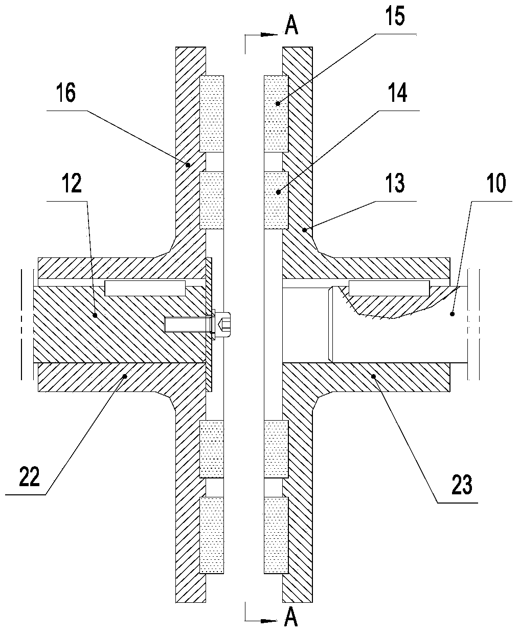
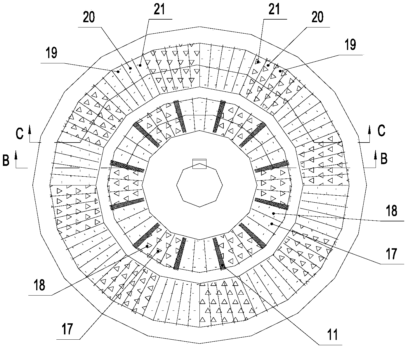
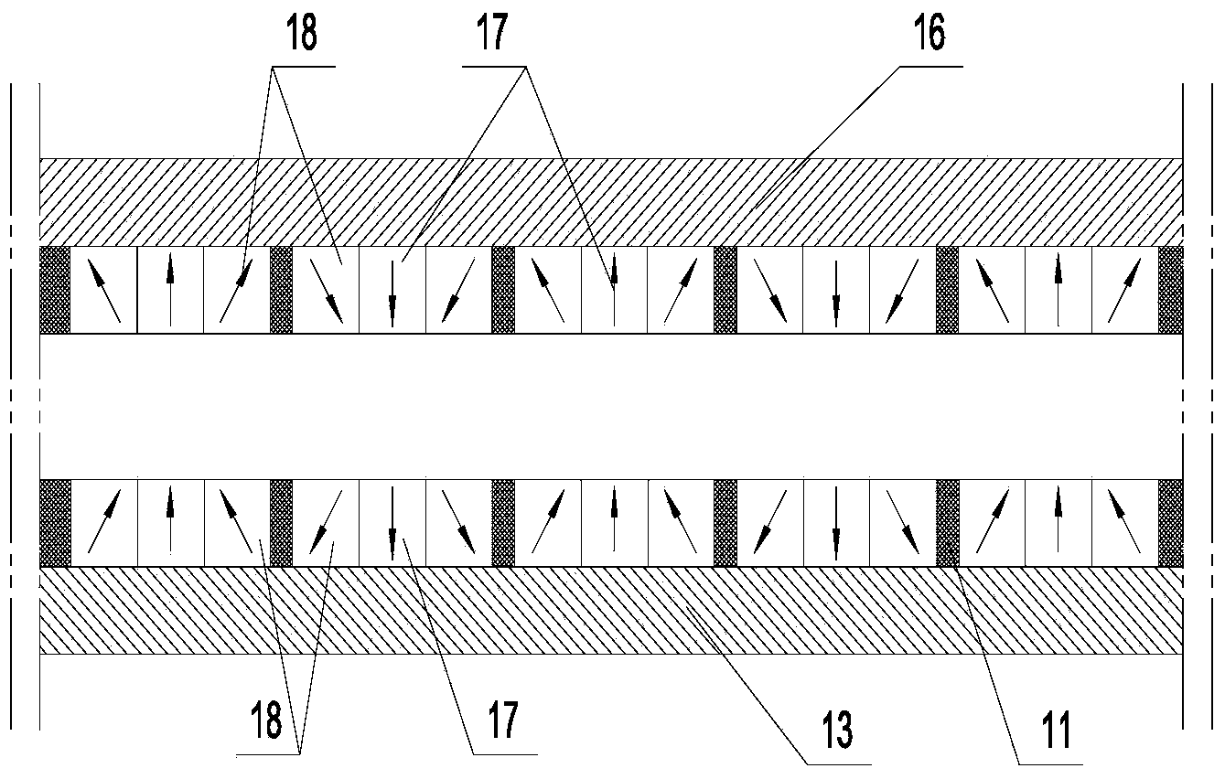
[0022] Such as Figure 1~4 As shown, a flat-disk type magnetism-concentrating magnetic circuit structure for a permanent magnet synchronous transmission device includes a left rotor 22 and a right rotor 23, the left rotor 22 and the right rotor 23 have the same structure, and the rotor disk is flat The disks are arranged opposite to each other in a disk-shaped structure. The left rotor 22 is composed of a disk-shaped left rotor disk 16, twelve sets of inner ring permanent magnet groups 14 and sixteen sets of outer ring permanent magnet groups 15. The ring permanent magnet group is bonded and fixed on the right side surface of the left rotor disc 16 through magnetically conductive glue, and is evenly distribute...


PUM


Abstract

The invention discloses a flat plate magnet collecting type magnetic circuit structure for a permanent magnet synchronous transmission device, and belongs to the technical field of permanent magnet transmission. According to the permanent magnet synchronous transmission device with the flat plate magnet collecting type magnetic circuit structure, magnetic field strength in a magnet collecting type magnetic circuit air gap is enhanced, transmission torque is increased, the appearance size of the transmission device is reduced, and manufacturing cost is lowered. The flat plate magnet collecting type magnetic circuit structure comprises a left rotor and a right rotor, the left rotor is composed of a left rotor plate and even permanent magnet sets, the right rotor is composed of a right rotor plate and even permanent magnet sets, and the permanent magnet sets on the left rotor plate correspond to the permanent magnet sets on the right rotor plate. The permanent magnet sets are all composed of two to five magnets in close contact, the number of the magnets included by the permanent magnet sets in the same magnetic coupling ring is the same, and the magnets are all distributed in the radial directions of the left rotor plate and the right rotor plate. The magnetizing polarity directions of the magnets in the same permanent magnet set are identical. The magnetizing polarity directions of the adjacent permanent magnet sets are opposite.

Description

technical field [0001] The invention belongs to the technical field of permanent magnet synchronous transmission, and in particular relates to a flat-disc type magnetism-concentrating magnetic circuit structure used in a permanent magnet synchronous transmission. Background technique [0002] Permanent magnet synchronous transmission is a technology that uses a high-intensity magnetic field to pass through a certain space distance and penetrate a certain material to transmit rotational or translational mechanical energy. Permanent magnet synchronous transmission technology has no direct contact, less vibration, smooth movement, high efficiency, no electromagnetic and noise pollution, vibration isolation, long life, maintenance-free, no leakage channel when used for sealing, and zero leakage in the process of energy transmission And other advantages, it has been successfully applied in transmission devices such as magnetic pumps, magnetic drive agitators and permanent magnet ...

Claims


Application Information

Patent Timeline
Patent Type & Authority Applications(China)
IPC IPC(8): H02K49/06
Inventor 张世伟赵克中王德喜
Owner LIAOYANG TAIKE LEINUO SCI & TECH
Why Eureka
Try Eureka